Image capturing device for a vehicle

a technology for capturing devices and vehicles, applied in the field of vehicle image capture devices, can solve problems such as vehicle detection, and achieve the effect of reducing light intensity, reliable and cost-effectiv

Inactive Publication Date: 2015-02-05
CONTI TEMIC MICROELECTRONIC GMBH
View PDF4 Cites 10 Cited by
  • Summary
  • Abstract
  • Description
  • Claims
  • Application Information

AI Technical Summary

Benefits of technology

[0012]One advantage of the invention is that moisture can be detected in a reliable and cost-efficient manner by means of an image capturing device comprising a single image sensor, i.e. by means of a mono camera.
[0013]In an advantageous embodiment, the image sensor comprises a plurality of sensor elements which are arranged next to each other in the form of a matrix and are sensitive to electromagnetic radiation. Filter elements are assigned to the sensor elements by means of a filter pixel matrix, so that each sensor element detects electromagnetic radiation from a specific wavelength range or with a specific direction of polarization. It is also possible that several adjacent sensor elements are assigned to an identical filter element of the filter pixel matrix. If the polarizers are included in the filter pixel matrix, the polarizers can be optimally distributed on the one hand and the color information of the detected image sensor signal is substantially retained on the other. Polarizers reduce the light intensity of non-polarized light by approx. 50%. In addition, another 10% is lost due to reflection and absorption. To ensure that the sensitivity of cameras for automobile applications is still high enough, in particular at night, a light loss of approx. 60%, as is the case in polarizing filters having a continuous surface, cannot be tolerated. If the color and polarizing filter elements are distributed in a pixel pattern instead, an approximately homogeneous signal height is achieved since the transmission loss of a polarizing filter element is in the order of magnitude of the color filter element which is no longer present.
[0014]In addition, the polarizers have hardly any effect on a grayscale image generated for the purpose of detecting edges and shapes.
[0015]Further advantageous configurations of the image capturing device of the invention are set out in the subclaims and in the exemplary embodiments.
[0016]The invention further relates to a method for detecting moisture on a road by means of an image capturing device of the invention. Said device comprises polarizing filters (h;v) with different orientations in at least two subareas in front of an image sensor. Once the image sensor has captured an image, moisture on the road is detected by comparing the intensities of the at least two subareas (h;v) that are polarized differently. The difference in intensity results from the fact that the portions that are polarized differently are reflected differently on the wet road. Light polarized in parallel (vertically) is transmitted to a greater degree, while light polarized at right angles (horizontally) is reflected to a greater degree on the wet surface and is thus detected to a greater degree by the image sensor.

Problems solved by technology

The drawbacks of this method are, among others, that a separate rain sensor is required to correct the coefficient of friction and that moisture on the vehicle is detected rather than moisture on the road.

Method used


Image

  • Image capturing device for a vehicle
  • Image capturing device for a vehicle

Examples


Embodiment Construction

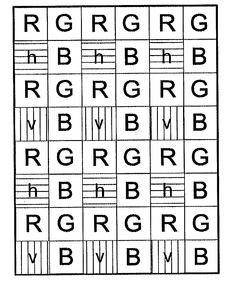
[0020]FIG. 1 shows a filter pixel matrix for the image sensor, corresponding to a modified Bayer color filter where each fourth pixel is provided with a polarizer. In the shown case, the green filter element in the second line of an original 2×2 Bayer color filter (R,G,G,B) has been replaced with a polarizer (R,G,h / v,B). The two directions of polarization are at right angles or horizontal (h, horizontal hatching) on the one hand and in parallel or vertical (v, vertical hatching) on the other. In the filter matrix of FIG. 1, the second green Bayer filter element has been replaced in such a manner that the lines including polarizers alternate: 1st line: no polarizers, 2nd line: horizontal polarizers (h), 3rd line: no polarizers, 4th line: vertical polarizers (v).

[0021]The polarizers are arranged in such a manner that those in one line are at right angles to those in the next. In case of non-polarized light, there will be no visible line-patterned brightness or intensity structure. In ...


PUM


Abstract

The invention relates to an image capturing device comprising an image sensor. A first polarizing filter is arranged in at least one first subarea in front of the image sensor while a second polarizing filter is arranged in at least one second subarea. The polarizing filters have different directions of polarization (h;v). The image capturing device of the invention comprises an evaluation unit which is able to detect the presence of polarized light by comparing the intensities of the at least two subareas that are polarized differently. In other words, the intensity in the subarea of the image sensor which receives electromagnetic radiation that has passed through the first polarizing filter is compared with the intensity in the subarea of the image sensor which receives electromagnetic radiation that has passed through the second polarizing filter.

Description

CROSS REFERENCE TO RELATED APPLICATIONS[0001]This application is the U.S. National Phase Application of PCT / DE2012 / 100194, filed Jul. 2, 2012, which claims priority to German Patent Application No. 10 2011 051 583.6, filed Jul. 5, 2011, the contents of such applications being incorporated by reference herein.FIELD OF THE INVENTION[0002]The invention relates to an image capturing device for a vehicle and a method for detecting moisture on a road.BACKGROUND OF THE INVENTION[0003]Accident prevention is an increasingly important aspect of driver assistance systems. Emergency braking systems make a major contribution in this regard. However, their effectiveness essentially depends on the coefficient of friction of the road surface. In particular in wet conditions, the coefficient of friction is much lower than that on a dry road.[0004]JP 2010-243463 A, which is incorporated by reference, shows a vehicle-mounted stereo camera where two pairs of lenses for different ranges of vision and tw...

Claims


Application Information

Patent Timeline
Patent Type & Authority Applications(United States)
IPC IPC(8): B60R1/00G06K9/00
CPCB60R1/00B60R2300/804B60R2300/8053G06K9/00791G01N21/21H01L27/14621G01N2021/1772G01N2021/1776H04N25/134G06V20/56
Inventor KROKEL, DIETER
Owner CONTI TEMIC MICROELECTRONIC GMBH
Why Eureka
Try Eureka