
Method of manufacturing a component

a manufacturing method and component technology, applied in the direction of additive manufacturing processes, manufacturing tools, transportation and packaging, etc., can solve the problems of unaccounted distortion of components during manufacture, incongruity of final components, and inability to achieve geometric and/or mechanical properties

Active Publication Date: 2015-02-05
ROLLS ROYCE PLC
View PDF4 Cites 45 Cited by
  • Summary
  • Abstract
  • Description
  • Claims
  • Application Information

AI Technical Summary

Benefits of technology

The patent is about a method that allows for in-situ inspection of a component during manufacture using advanced techniques. This means that the shape of the component can be measured while it is being made. This can help to reduce defective components from being generated, resulting in cost and efficiency improvements. By measuring the shape of the component during manufacture, a decision can be made on the fate of the component before it is finished. This also eliminates the need for a separate measuring step after the component is made. The method involves generating a virtual 3-D model of the manufactured component using data from the measured solid layers. This means that the precise shape of the final component can be determined without needing an additional measurement step.

Problems solved by technology

Manufacturing components using ALM has many advantages, including the possibility to manufacture complex 3D shapes with little or no bespoke tooling, but the final components may not consistently have the desired geometric and / or mechanical properties.
The high levels of energy involved in the ALM process may lead to unwanted and / or unaccounted distortion in the component during manufacture.
Furthermore, geometric differences may occur between two different versions of the same component manufactured on the same machine with the same process parameters simply as a result of the stochastic natural of distributing and melting tens of millions of powder grains with small (unwanted) variations in process parameters and powder particles.
This extra inspection step requires the use of an additional machine, and adds significant time to the manufacture of each and every component.
Furthermore, the inspection may reveal that at least some of the components may not be within the allowable geometric tolerance, meaning that those fully manufactured components may become scrap.
Thus, the power of the scanning electron beam may be insufficient to perform selective melting of the powder layer, but (where present) the power of the melting electron beam may be sufficient to perform selective melting of the powder layer.
This may result in a particularly compact and / or low cost additive layer manufacturing machine.

Method used


Image

  • Method of manufacturing a component
  • Method of manufacturing a component
  • Method of manufacturing a component

Examples


Embodiment Construction

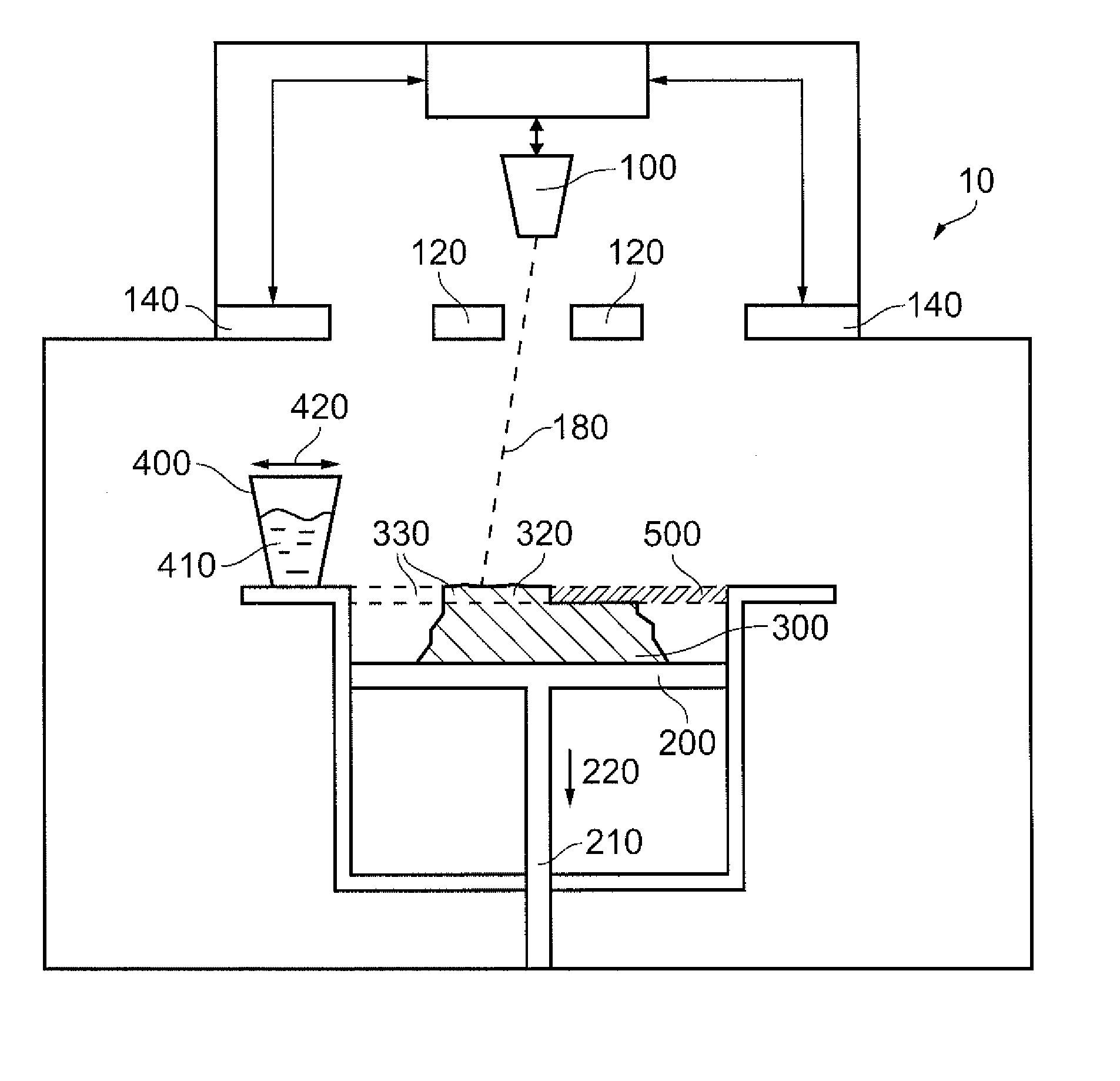
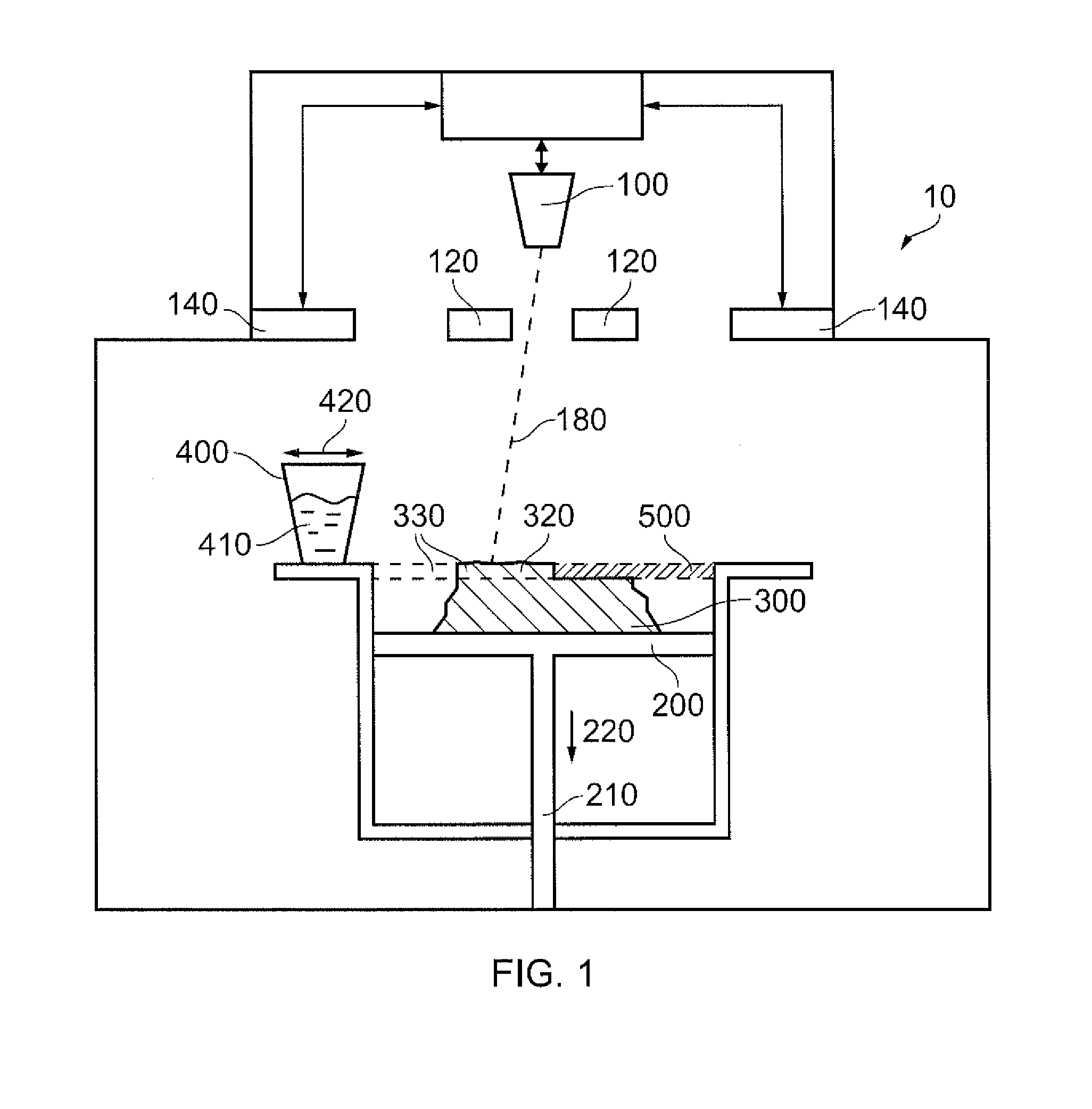
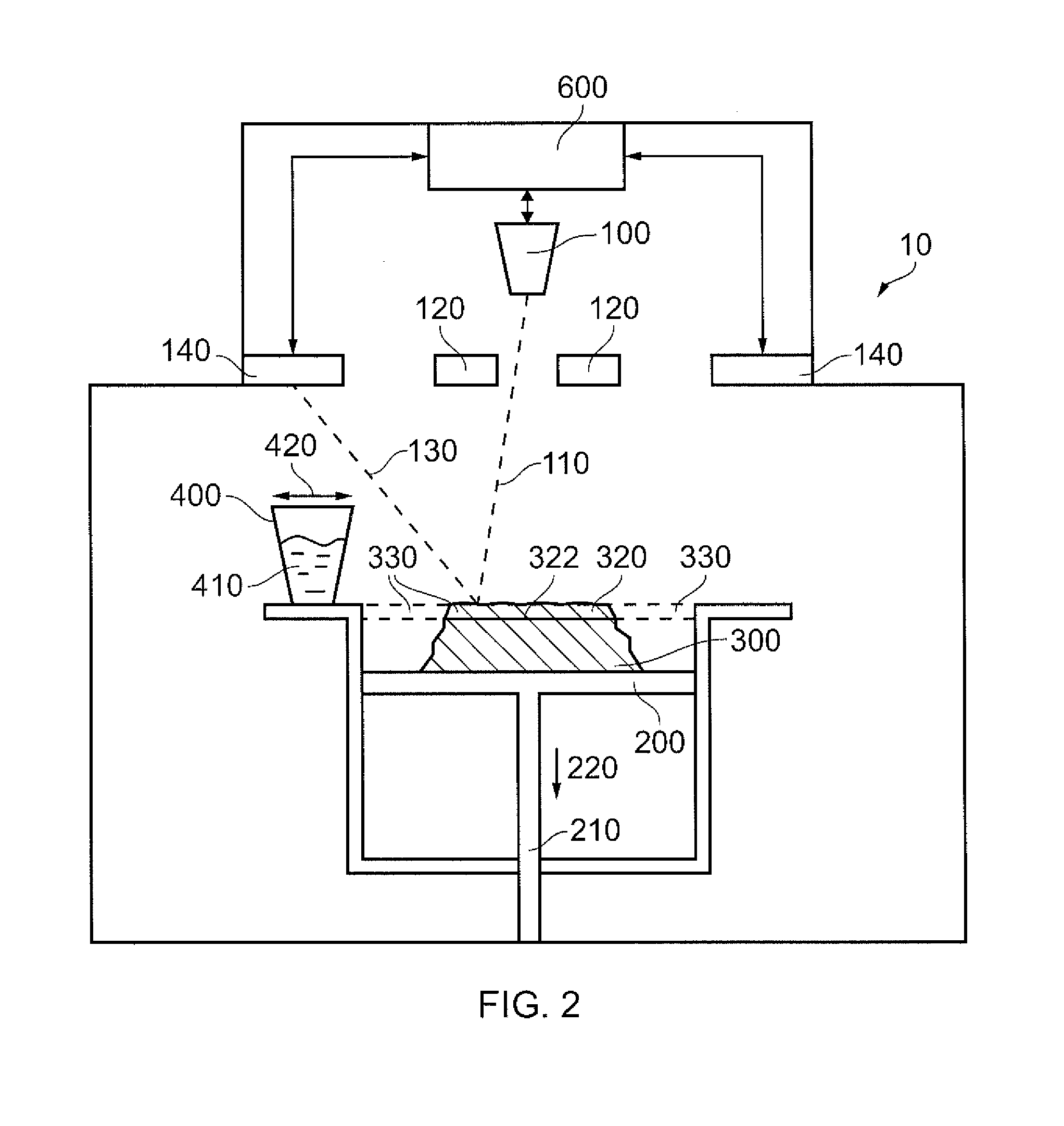
[0055]As explained elsewhere herein, additive layer manufacturing (ALM) methods may be used to manufacture components by sequential selective melting of thin powder layers. For example, an EBM machine may be used to manufacture a metallic component by sequential selective melting of thin metal powder layers.

[0056]An example of an additive layer manufacturing machine (or ALM machine) 10 for use in such a method is shown in FIG. 1. The ALM machine 10 comprises an electron beam source 100 for generating an electron beam 180 (which may be referred to as a melting electron beam). In use, the electron beam 180 is focussed using focusing elements 120, such as lenses and / or mirrors, towards a component 300 being manufactured. Specifically, the electron beam 180 is focussed onto a layer of powder (for example a layer of powder metal) 500 to be melted by the electron beam 180 which subsequently melts to form a solid layer (for example a solid metal layer) of the component 300. The powder laye...


PUM

PropertyMeasurementUnit
Poweraaaaaaaaaa
Shapeaaaaaaaaaa
Mechanical propertiesaaaaaaaaaa

Abstract

An additive layer manufacture (ALM) machine comprises an energy source (180) for selectively melting a layer of metal powder (500), and an electron beam (110) for determining the shape of the selectively melted solid layer (320) once it has solidified. The shape is determined by detecting backscattered electrons (130) from the interaction between the electron beam (110) and the solid layer (320). If the shape of the solid layer (320) is outside a determined tolerance, it may be corrected before proceeding. The process may be repeated to generate a finished component (300) with good mechanical properties and accurate geometry.

Description

CROSS-REFERENCE TO RELATED APPLICATIONS[0001]This application is based upon and claims the benefit of priority from British Patent Application Number 1313841.7 filed 2 Aug. 2013, the entire contents of which is incorporated by reference.BACKGROUND OF THE INVENTION[0002]1. Field of the Disclosure[0003]The present invention relates to a method of manufacturing a component. In particular, the present invention relates to manufacturing a component using additive layer manufacture.[0004]2. Description of the Related Art[0005]Additive layer manufacturing (ALM) methods using electron beam melting (EBM) may be used to manufacture metallic components by sequential selective melting of thin metal powder layers. According to such a method, a layer of metal powder is deposited onto a surface (or plate), and an electron beam is used to selectively melt the powder layer. The melted material then solidifies so as to form a metallic layer of the desired shape. A further layer of powder is then depo...

Claims


Application Information

Patent Timeline
IPC IPC(8): B23K15/00H01J37/28
CPCB23K15/0086H01J37/28B23K15/002B33Y10/00B22F2998/00Y10T428/12389B29C64/153H01J37/304Y02P10/25B22F10/10B22F10/28B22F12/41B22F2003/247B22F3/15
Inventor BLACKMORE, MICHAEL LEWIS
Owner ROLLS ROYCE PLC
Learn More