Electrified rail, particularly for powering metal shelving units, and method for its manufacturing

a technology of electric insulation and electric rail, which is applied in the direction of application, show cabinets, coupling device connections, etc., can solve the problems of poor resistance to mechanical deformation, poor safety in terms of electric insulation, etc., and achieve poor resistance to mechanical deformation, poor safety, and poor resistance to overheating

Active Publication Date: 2015-02-05
IMOLA RETAIL SOLUTIONS SRL
View PDF10 Cites 6 Cited by
  • Summary
  • Abstract
  • Description
  • Claims
  • Application Information

AI Technical Summary

Benefits of technology

The patent text is saying that electric wires should not stick out from their slots and should only be accessible through narrow channels to prevent any accidental contact. This means that the electric contacts of external devices can only touch the wires through these narrow channels, which results in a safer and more organized wiring system.

Problems solved by technology

All the known electrified rail use an electrically insulating PVC or similar plastic body, which offer a poor safety in terms of electric insulation, which sometimes are not self-extinguishing, and have poor capacity to resist overheating, which can develop for possible failures or overload.
Moreover, they have poor resistance to mechanical deformation, already at temperatures near to 100° C. In the known electrified rails, electric wires are inserted into the plastic body after its formation, taking advantage of the deformability and of the elasticity at the relatively cold temperature of the plastics itself.
In order to assume the necessary linear form of mechanical resistance, to the electrically insulating plastic body of known type an external support and rigid body is paired, generally made of metal, with further manufacturing problems and with deducible difficulties in realizing electrified rails having a limited section.

Method used


Image

  • Electrified rail, particularly for powering metal shelving units, and method for its manufacturing
  • Electrified rail, particularly for powering metal shelving units, and method for its manufacturing
  • Electrified rail, particularly for powering metal shelving units, and method for its manufacturing

Examples


Embodiment Construction

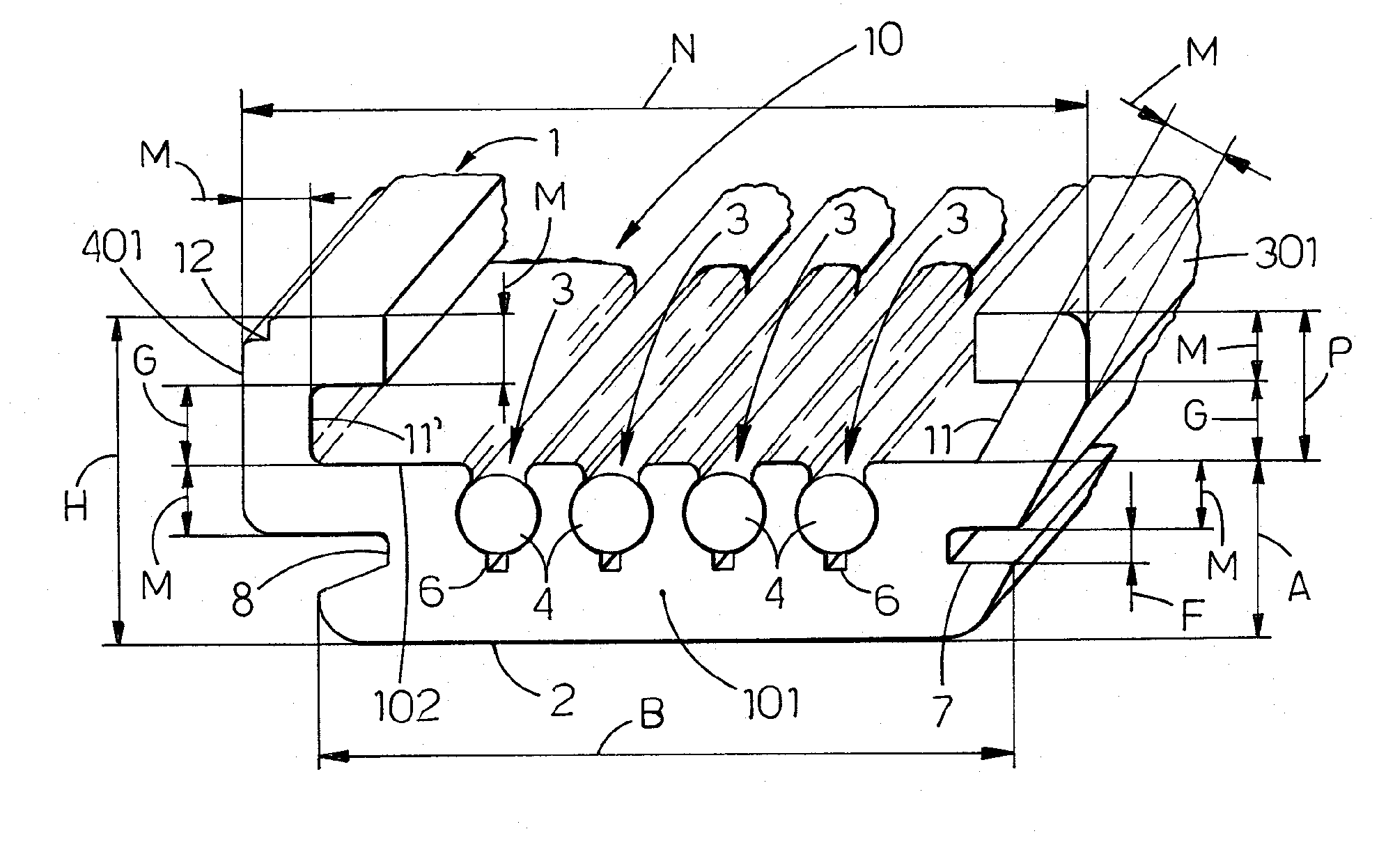
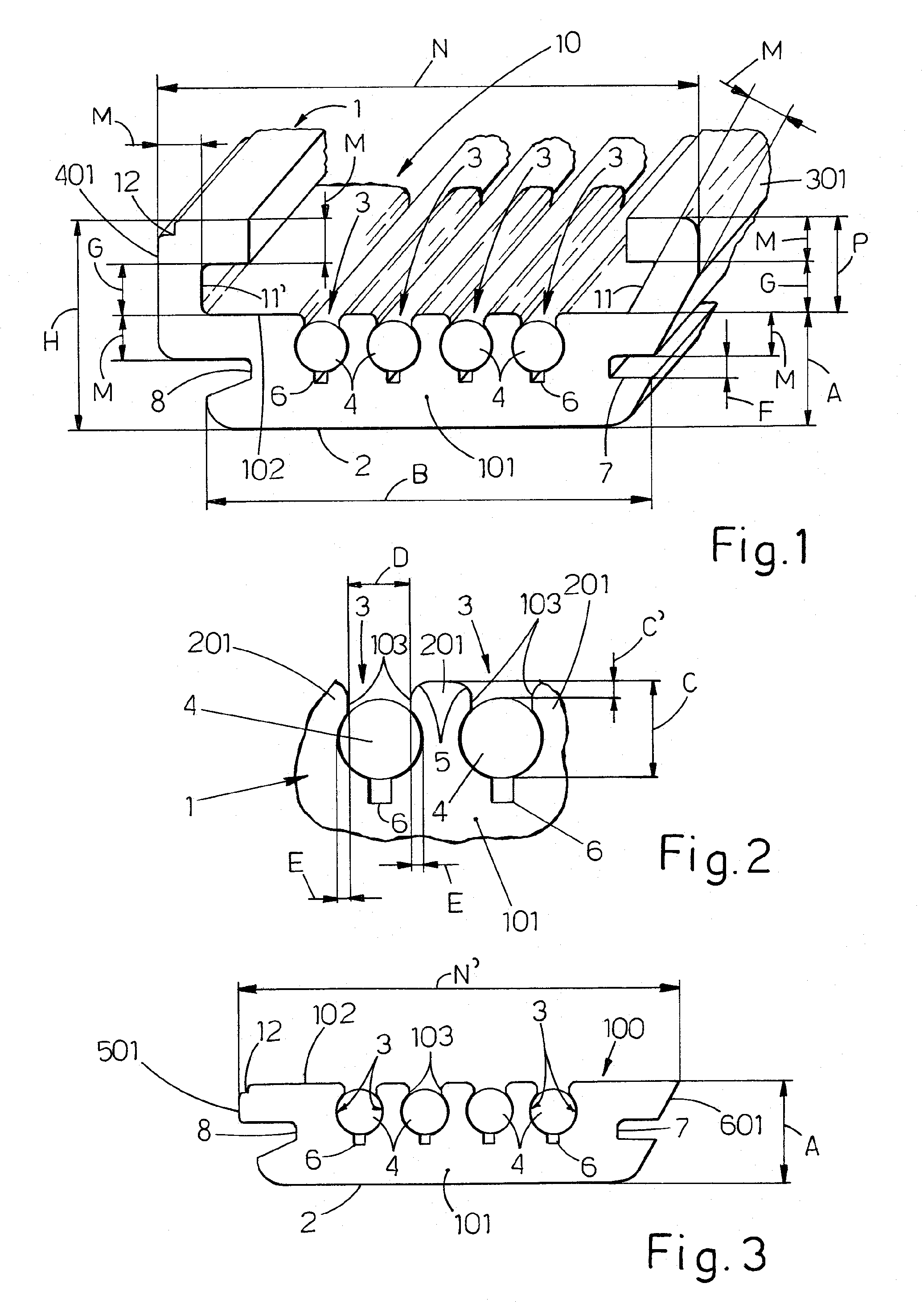
[0035]With reference to FIGS. 1 and 2, the electrified rail 1, according to the present invention, produced through extrusion of a PC or PPO resin, or other heat-resistant, self-extinguishing resin, having good mechanical and good electrically insulating characteristics, has a substantially U- or C-profile (see in the following). The rail has a longitudinal channel 10 and a base 101 of thickness A of about 4-4.5 mm, e.g. about 4.2 mm, a width B of about 16 mm, a planar external basal surface 2 with a superior side 102, internal to the profile; this side is planar too, and is substantially parallel to said external side 2. The rail is provided, e.g. with symmetrical disposition, with a plurality of longitudinal slots 3, e.g. four slots, capable of precisely holding corresponding metal conductors 4, e.g. in the form of copper wires or strands (see in the following). Good results were obtained using copper wires 4 having a section of 1.5-1.8 mm, e.g. about 1.78 mm, protected by a subtl...


PUM

PropertyMeasurementUnit
Angleaaaaaaaaaa
Lengthaaaaaaaaaa
Lengthaaaaaaaaaa

Abstract

An electrified rail, particularly for the electrification of metal shelving units provided on their front of electronic labels, displays and / or other peripherals, the rail being of the kind comprising a body (1, 100) of electrically insulating plastic material, provided with longitudinal slots (3) suitably distanced to each other, in every one of which a wire or strand (4) of electrically conducting metal which is surrounded for more than 180° of its cross section by the internal walls of the respective slot (3), to be friction-held in it, so that for the remaining section the same wire (4) is free and can be reached by an electric contact useful to connect the wire to a plug or to an electric or electronic device, fixed to said body (1, 100) of the rail, characterized in that the body (1, 100) of the rail is formed in a monolithic way of polycarbonate (PC) or polyphenylene oxide (PPO) and / or other resins having suitable mechanical characteristics, with high electric insulation and with high heat resistance, preferably self-extinguishing, and in that said slots (3) containing electric wires (4) are such and are disposed in such a way that, if after the extrusion step the still hot rail is transversally flexed, slots (3) themselves outwardly open to ease the insertion of electric wires, slots (3) being provided on their bottom of longitudinal middle grooves (6) having the width and depth necessary to allow a transversal elastic deformation of the rail itself during its manufacturing, with the formation of an oscillating fulcrum in correspondence of grooves (6), which is parallel to the longitudinal axis of the grooves (6), whose width is inferior to the width (D) of the outward opening mouth of slots (3) for holding electric wires (4), said slots (3) being positioned one beside the other, and after the surrounding and holding of the wires (4) the slots are open on a visible planar side (102) of the rail body (1, 100) with longitudinal mouths (103) having a width (D) always inferior to the diameter of wires (4); the depth of slot (3) being perpendicular to said visible side (102) and having a value (C′) sufficient for wire (4) to be ditched and protected in the slot (3) surrounding the wires (4) for more than 180° of their section, the wires (4) being held in slots (3) by the toughness and structural non-deformability of the material forming the monolithic body (1, 100) of the rail itself, while through the narrow mouths (103) of said slots (3) every electric wire (4) can be reached by the spring-loaded contacts (32) of plugs (29) or of devices (33) mounted on the monolithic body itself (1, 100) of the rail, wherein the base (2) of body (1, 100) of the rail is provided on its inferior side (2) with small longitudinal grooves (9) having dimensions equal or different from the bottom grooves (6) of slots (3) holding electric wires (4), said bottom longitudinal grooves being in an offset symmetrical position with respect to the slot longitudinal grooves (6), capable of allowing a transversal deformation of the rail during its production.

Description

CROSS REFERENCE TO RELATED APPLICATIONS[0001]The present application claims priority to Italian Patent Application No. BO2013A000415 filed Jul. 31, 2013, the contents of which are expressly incorporated herein by reference.STATEMENT RE: FEDERALLY SPONSORED RESEARCH / DEVELOPMENT[0002]Not Applicable.BACKGROUND OF THE INVENTION[0003]The present invention is classified under international classes H01R and G09F, and relates to an electrified rail, in particularly for metal shelving units which have to be provided, on the side facing the public of the shelves supporting goods, with electronic labels, displays and / or other peripherals. Moreover the present invention relates to the method for producing such electrified rail.[0004]As prior art, the following documents are cited.[0005]Patent application WO 1994 / 22125 titled “Information display rail system” describes an extruded rail with a C-profile, to be fixed on the front side of the shelves. The rail is provided with a longitudinal top ri...

Claims


Application Information

Patent Timeline
IPC IPC(8): H01R25/16H01R4/48H01R43/00H01R13/03
CPCH01R25/164H01R43/00H01R4/48H01R13/035H01R25/14Y10T29/49181A47F11/00H01R13/436
Inventor BONZI, GIANCARLONANNI, EROS
Owner IMOLA RETAIL SOLUTIONS SRL
Why Eureka
Try Eureka