Method for producing structured optical components

Active Publication Date: 2015-02-12
FRAUNHOFER GESELLSCHAFT ZUR FOERDERUNG DER ANGEWANDTEN FORSCHUNG EV
View PDF0 Cites 9 Cited by
  • Summary
  • Abstract
  • Description
  • Claims
  • Application Information

AI Technical Summary

Benefits of technology

The present invention aims to provide a cost-effective and flexible method for producing optical components, especially covers, with displaced and / or inclined regions and high surface quality. The technical effect is to overcome the shortcomings of previous methods and improve production efficiency.

Problems solved by technology

However, such surfaces can only be implemented in standard silicon wafers having specific angles of inclination, which are predefined by the crystal structure of silicon.
The production of corresponding optical components based on glass, for example, borosilicate glass, by means of etching methods typically results in surfaces, the roughness of which is not satisfactory for optical applications (see documents Xinghua Li, Takashi Abe, Masayoshi Esashi “Deep reactive ion etching of Pyrex glass using SF6 plasma”, Sensors and Actuators A87, 2001, pp.
A disadvantage of the method is that the implementation of the reinforcing elements is linked to a relatively high material outlay, since large regions of the starting layer must be removed by etching processes.

Method used


Image

  • Method for producing structured optical components
  • Method for producing structured optical components
  • Method for producing structured optical components

Examples


Embodiment Construction

[0161]Without restriction of the generality, the invention will be described in greater detail hereafter on the basis of examples.

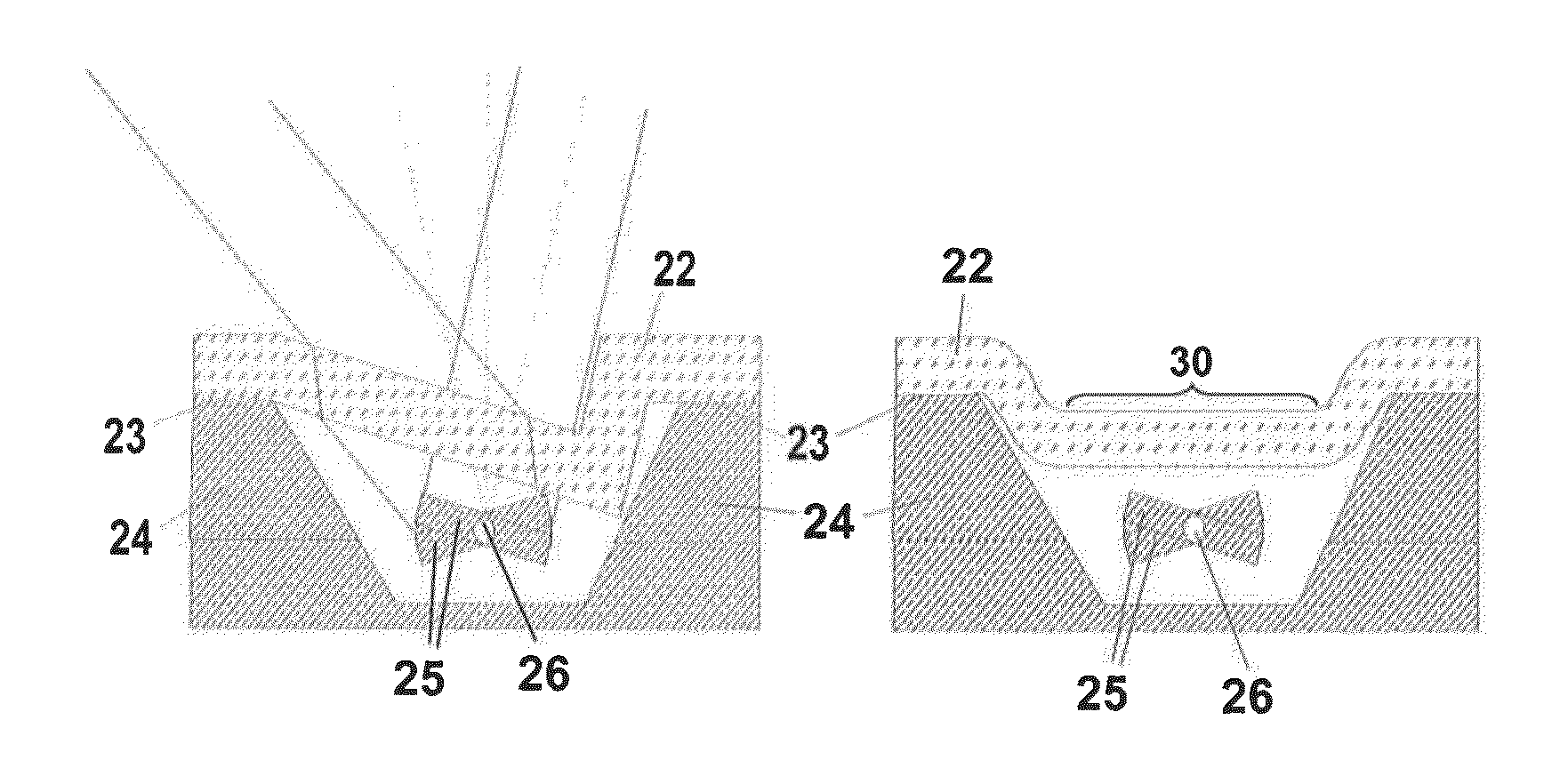
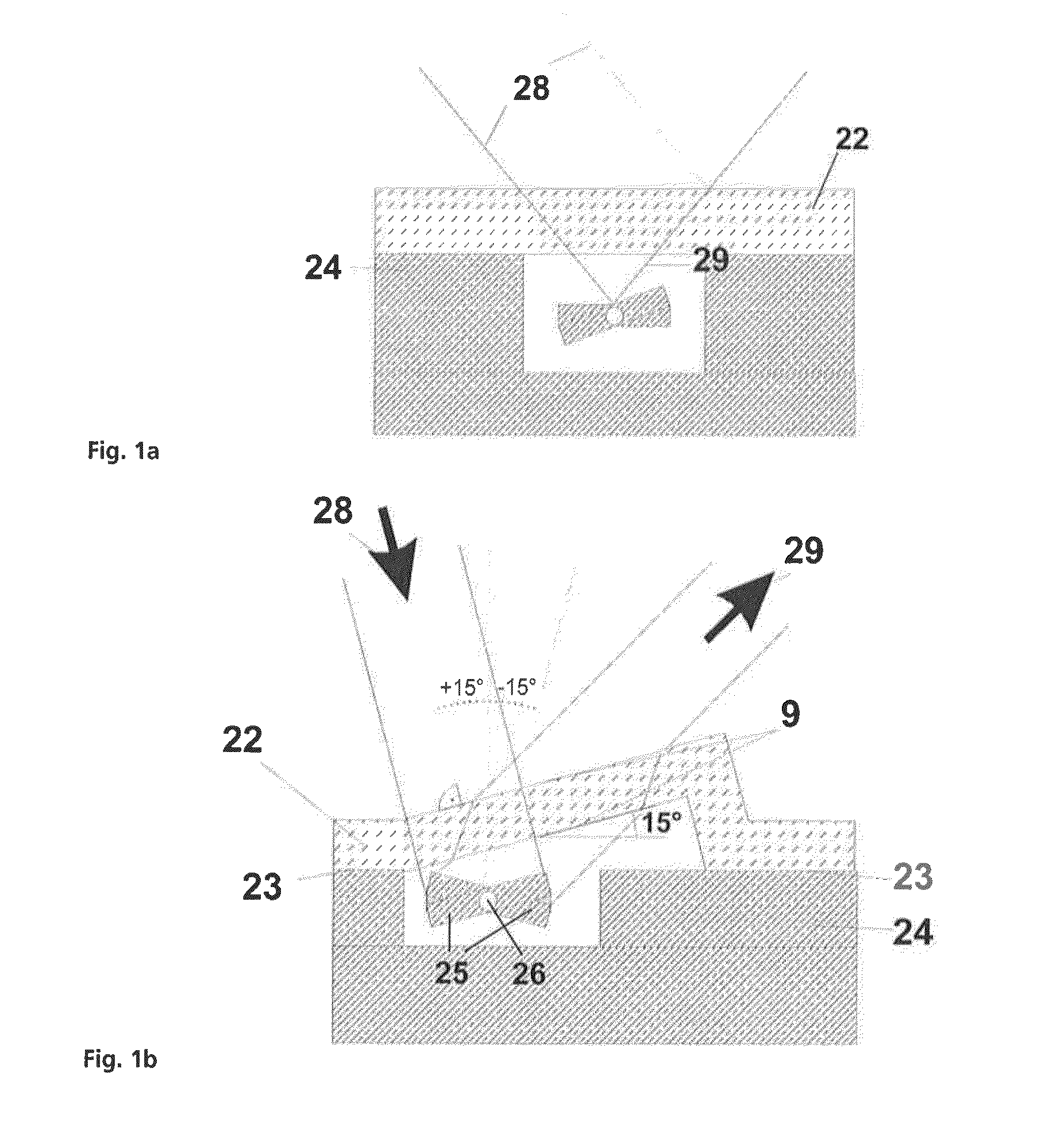
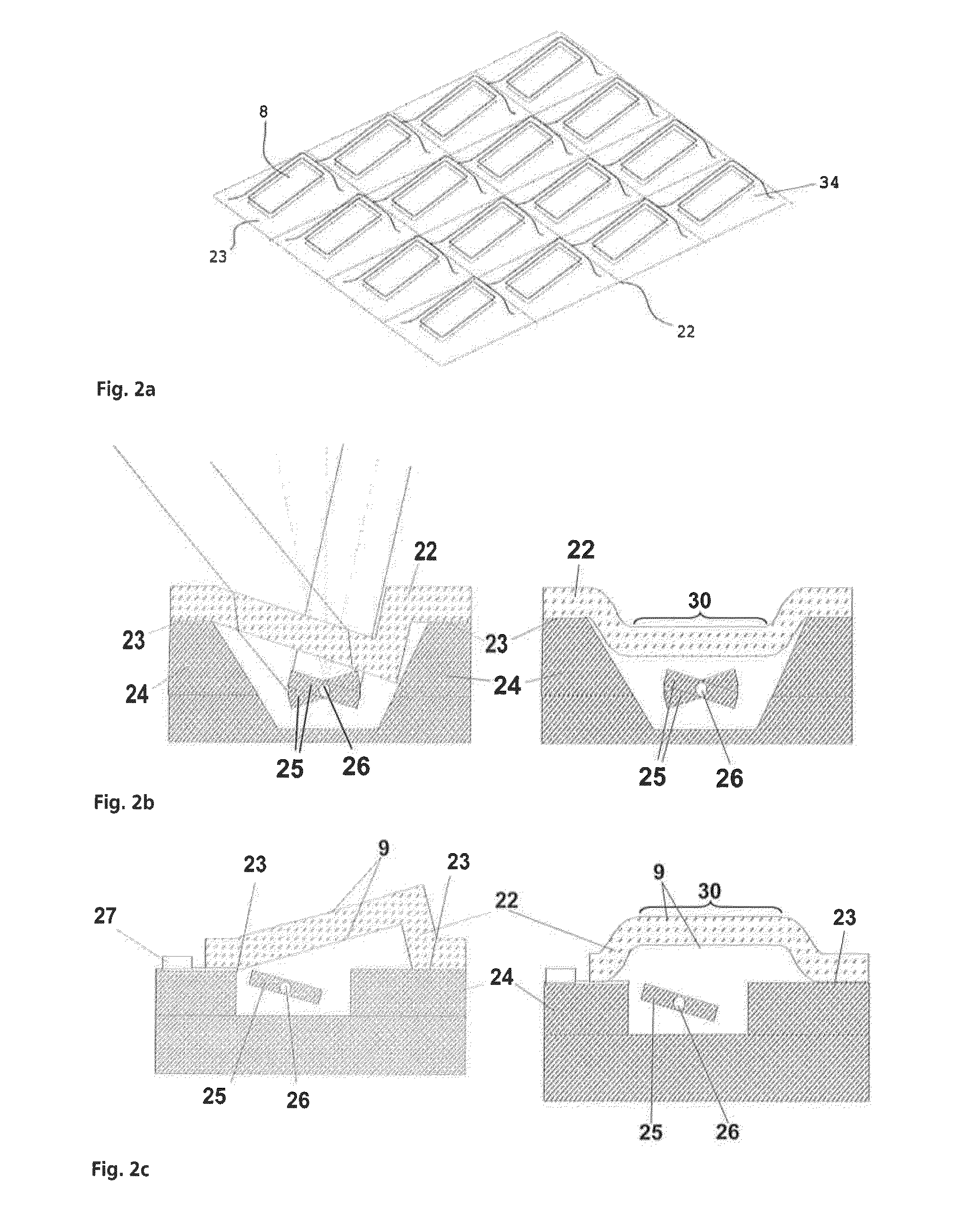
[0162]FIG. 2 shows a cover 22 produced using the method according to the invention having inclined optical windows 8 and displaced optical windows 30 and the use thereof to encapsulate a micromirror 25.

[0163]FIG. 3 shows the step sequence of a process variant to produce a cover 22 having inclined optical windows 8 according to the method according to the invention as claimed in claim 1.

[0164]FIG. 4 shows the step sequence of a process variant to produce a cover 22 having inclined optical windows 8 according to the method according to the invention as claimed in claim 1 with the use of support structures 13.

[0165]FIGS. 5-5.4 show the step sequence of further process variants to produce a cover 22 having displaced optical windows 30 according to the method according to the invention as claimed in claim 1 (FIGS. 5-5.1), claim 2 (FIGS. 5.2-5.3), and claim 3 o...


PUM

PropertyMeasurementUnit
Nanoscale particle sizeaaaaaaaaaa

Abstract

The method according to the invention is used for producing optical components, in particular covers for encapsulating micro-systems, wherein at least one reinforcing element, which is produced before being arranged, is arranged on a first substrate, as a result of which a stack is produced. This stack is heated after being connected to a second substrate, as a result of which the first substrate is deformed such that at least one region, covered by the reinforcing element, of the first substrate is moved and / or is inclined or the first substrate is brought into contact with the reinforcing element. In an alternative method according to the invention, the reinforcing element is arranged on the second substrate, wherein this stack is then connected to the first substrate. The first substrate is subsequently heated and deformed such that a region of the first substrate is brought into contact with the reinforcing element.

Description

TECHNICAL AREA[0001]The invention relates to a method for producing structured optical components, in particular covers for encapsulating microsystems, which have to fulfill an optical function in particular.[0002]A cover for encapsulating microsystems (for example, MOEMS, MEMS), which are typically arranged on a carrier substrate, is generally to offer at least protection against contaminants and simultaneously is not to impair the mechanical and / or optical functionality of the microsystems. If the functionality of the microsystems is not to be restricted only to movements in or parallel to the carrier substrate plane, respectively, but rather is also to provide movements perpendicular to the carrier substrate plane, a cover must ensure freedom of movement typically corresponding to the microsystems. This requires structuring methods which enable a high surface quality of the optically functional regions, for example.PRIOR ART[0003]If the microsystems are to exert an optical functi...

Claims


Application Information

Patent Timeline
IPC IPC(8): G02B27/00G02B26/08B81C1/00G02B1/11
CPCG02B27/0006B81C1/00793G02B26/0833G02B1/118G02B5/0242G02B5/0278G02B26/0841B81C1/00317B81B2201/042B81B2203/0384Y10T29/49826B29D11/0074B29D11/00
Inventor QUENZER, HANS JOACHIMHOFMANN, ULRICHSTENCHLY, VANESSA
Owner FRAUNHOFER GESELLSCHAFT ZUR FOERDERUNG DER ANGEWANDTEN FORSCHUNG EV
Why Eureka
Try Eureka