Active resistance dynamometer for wheel testing

Active Publication Date: 2015-02-12
BOREALIS TECH LTD
View PDF7 Cites 8 Cited by
  • Summary
  • Abstract
  • Description
  • Claims
  • Application Information

AI Technical Summary

Benefits of technology

[0014]It is yet another object of the present invention to provide an active resistance dynamometer capable of testing wheel traction control in a powered or non-powered wheel under simulated realistic conditions.
[0015]It is yet a further object of the present invention to provide a

Problems solved by technology

These dynamometer systems have real world limitations, however.
In situations in which a machine or system must also be able to perform under fixed speed conditions, the use of a fixed inertial load cannot determine machine or system performance.
Testing a machine, device, or system at a speed that is variably set by a variable load is not possible with the systems described.
A direct motor type of dynamometer, which has two opposing motors and is typically used to test one of the motors, may effectively test the motor, but cannot effectively test other structures, such as, for example, vehicle wheels, load on a wheel due to brakes, and the like.
This capability is not provided by currently available dynamometer

Method used


Image

  • Active resistance dynamometer for wheel testing
  • Active resistance dynamometer for wheel testing
  • Active resistance dynamometer for wheel testing

Examples


Embodiment Construction

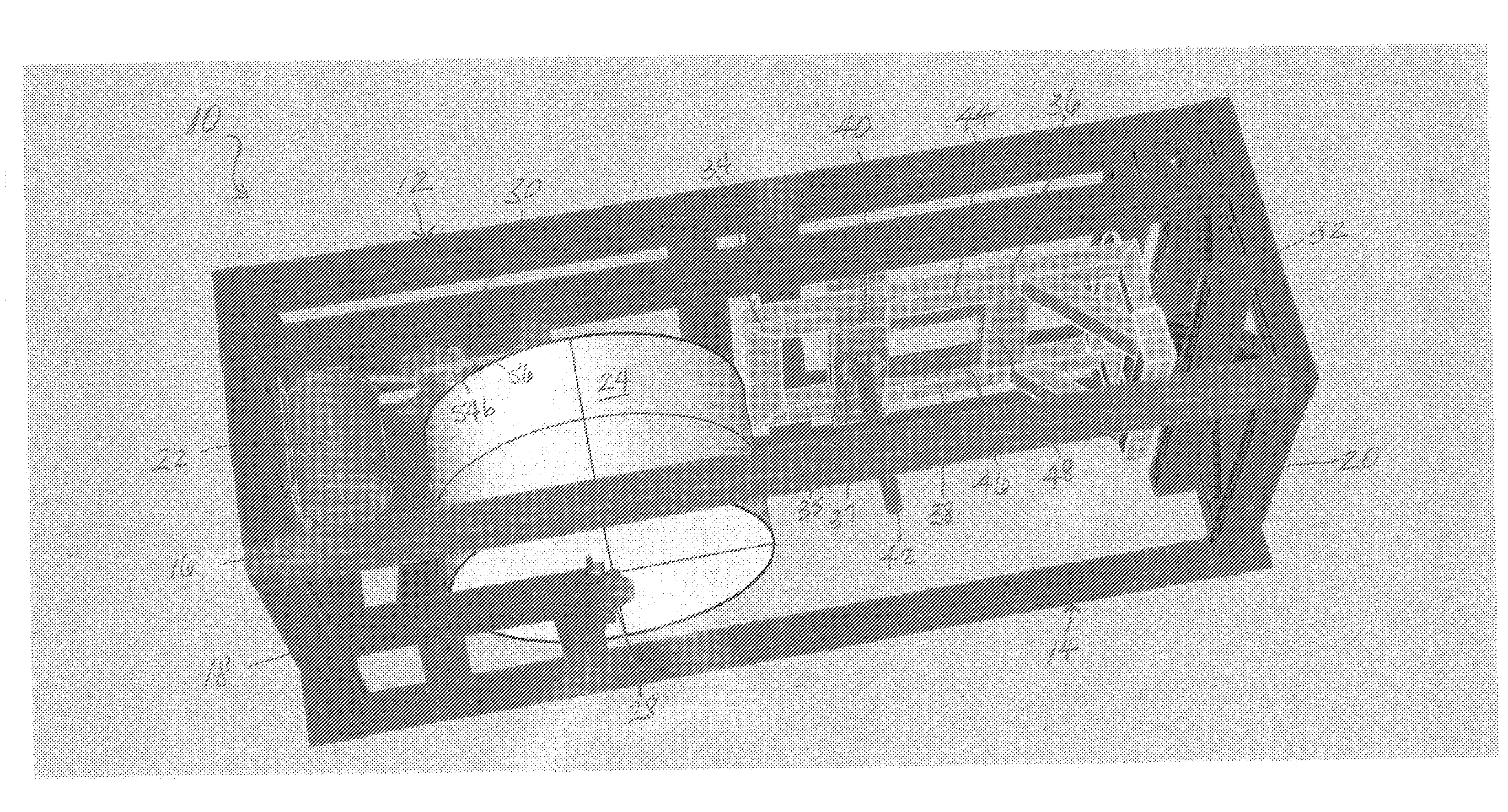
[0023]The active resistance dynamometer of the present invention provides a versatile testing and evaluation system for wheels and a range of wheel-connected and wheel-related structures and functions. Unlike available testing and evaluation systems, the present system provides an apparatus and method for testing wheel and wheel-connected structures and functions under simulated conditions that are more realistic than has heretofore been possible. The present system has the capability to vary either and / or both the speed of the wheel or wheel-connected structure under test and the load on the wheel or wheel-connected structure. Consequently, load tests can be done during acceleration or deceleration situations or at a fixed speed. The load on the wheel can be varied while the speed is fixed, and speed can be set by a variable load instead of inertial mass.

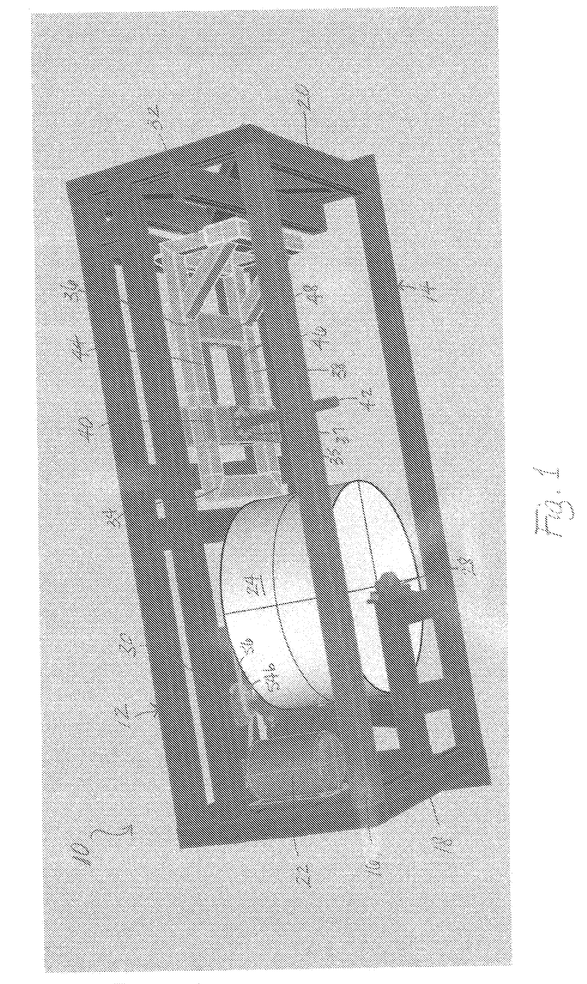
[0024]Referring to the drawings, FIG. 1 illustrates the active resistance dynamometer 10 of the present invention from a top pers...


PUM


Abstract

A wheel testing system and method are provided that simulates realistically conditions likely to be encountered during operation of vehicle wheels, especially powered drive wheels and wheel-connected structures. The system may include an integral support frame designed to adjustably mount wheels or wheel-connected structures to be tested, a load motor drivingly connected to an inertial load, and an adjustable mounting sled configured to adjustably mount a test wheel or a wheel-connected structure with an hydraulic system actuatable to adjust the location of the test wheel relative to the inertial load to vary or fix the load on the test wheel desired. Speed of the test wheel can be varied or fixed by controlling the speed of the load motor. System measurement and data collection electronics measure a range of selected wheel parameters and gather data for transmission to a processor or non-transitory storage medium for processing and evaluation.

Description

PRIORITY CLAIM[0001]This application claims priority from U.S. Provisional Application No. 61 / 617,024, filed Mar. 28, 2012, the disclosure of which is fully incorporated herein.TECHNICAL FIELD[0002]The present invention relates generally to systems for testing wheels and other rotational structures and specifically to an active resistance dynamometer for testing wheels and wheel-connected or wheel-related structures and functions.BACKGROUND OF THE INVENTION[0003]Dynamometers have long been used to determine the force, torque, and power produced by rotating machines and other rotating devices and systems of various types for testing, calibration, and similar purposes. Most of these kinds of dynamometers are equipped with some way to measure the operating torque and rotational speed or angular velocity of the unit or system to be tested or evaluated. Power is then calculated from these measurements. Either torque or speed can be maintained constant during operation of the dynamometer ...

Claims


Application Information

Patent Timeline
IPC IPC(8): G01M17/013G01L5/28G01L5/26G01N3/00
CPCG01M17/013G01L5/26G01L5/28G01N3/00G01M17/0074G01L3/00G01M17/00
Inventor EDELSON, JONATHAN SIDNEYPERKINS, SCOTTSWEET, ROBERT M.COX, ISAIAH W.
Owner BOREALIS TECH LTD
Why Eureka
Try Eureka