
Parallel micro-robot with 5-degrees-of-freedom

a micro-robot and parallel structure technology, applied in the direction of micromanipulators, joints, program-controlled manipulators, etc., can solve the problems of increased manufacturing cost, spatial restrictions on operation and installation, etc., to reduce the innovative number of actuators, minimize surgical space, and high accuracy

Inactive Publication Date: 2015-02-12
KOHYOUNG TECH +1
View PDF12 Cites 13 Cited by
  • Summary
  • Abstract
  • Description
  • Claims
  • Application Information

AI Technical Summary

Benefits of technology

The present invention is a micro-robot with a parallel structure and five degrees of freedom that can achieve high accuracy by adjusting the angle of its operating plate using two shafts rotating connection means. This design reduces the number of actuators needed to control the angle of the operating plate and allows for more precise control of its orientation and translation motion. Additionally, the design prevents the generation of gaps between the shafts and prevents the load from rolling, resulting in further precise control. The use of a lightweight structure and small-scale actuators also minimizes surgical space and installation restrictions.

Problems solved by technology

Therefore, manufacturing cost is increased as well as spatial restriction on operating and installing may be occurred when the surgical robot is designed with more than 5 degrees of freedom and the surgical robot becomes large size.

Method used


Image

  • Parallel micro-robot with 5-degrees-of-freedom
  • Parallel micro-robot with 5-degrees-of-freedom
  • Parallel micro-robot with 5-degrees-of-freedom

Examples


first embodiment

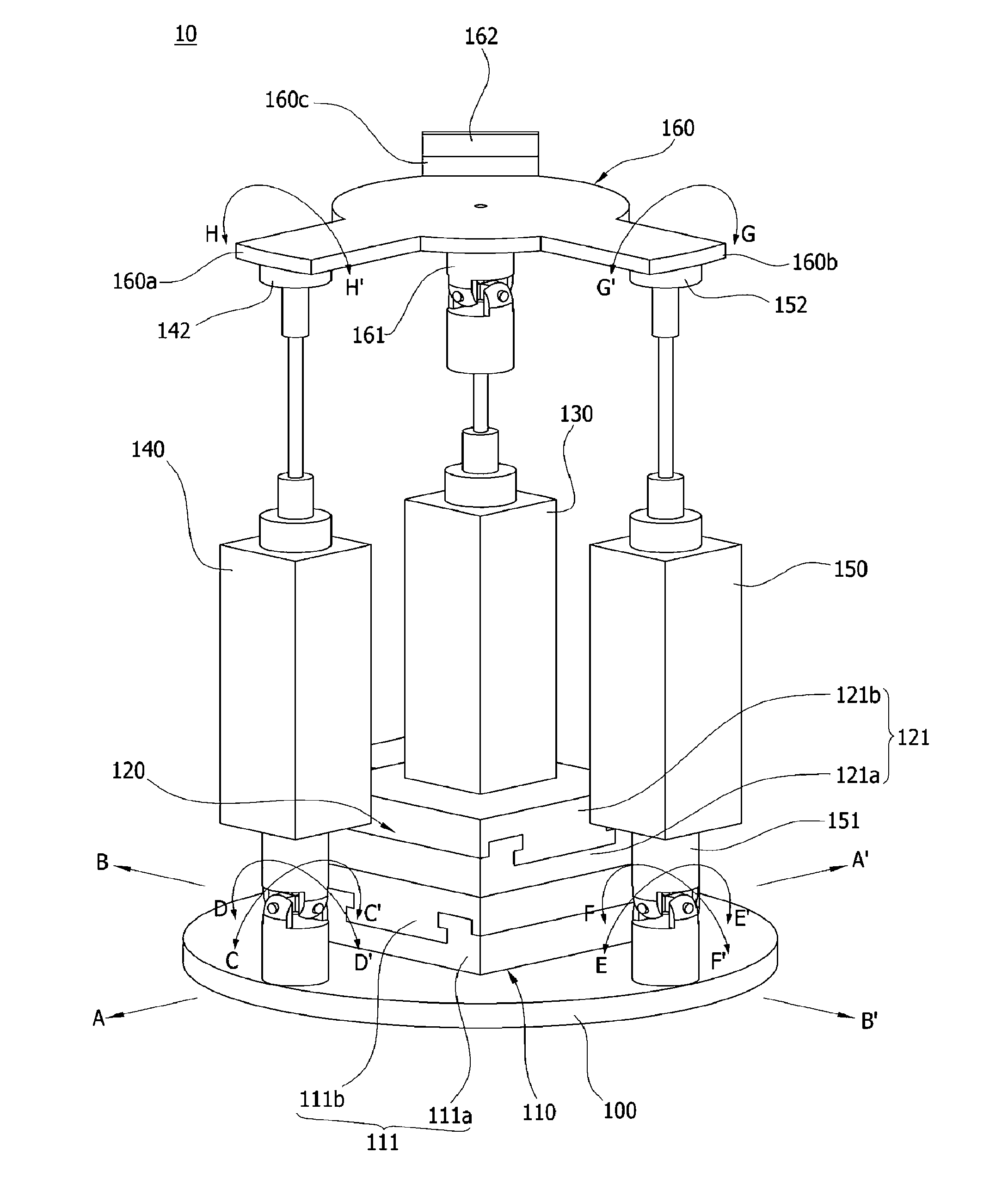
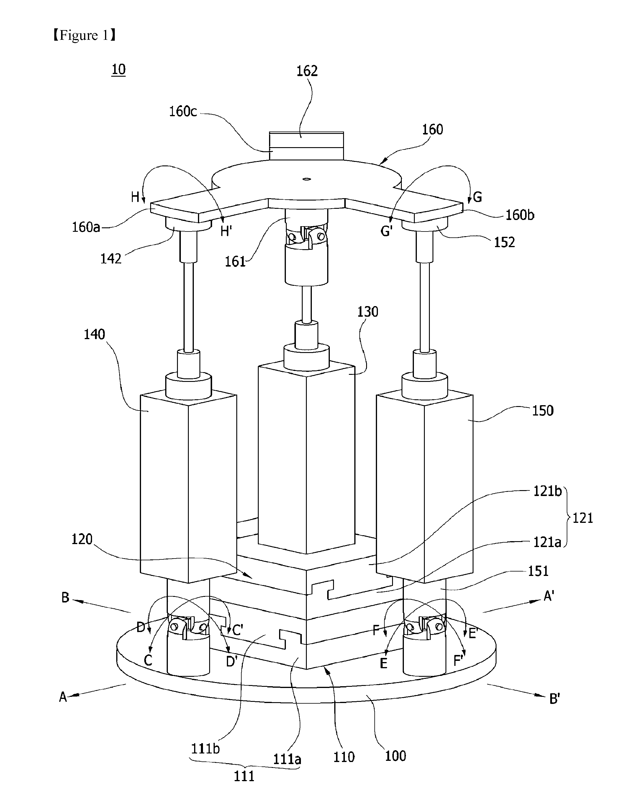
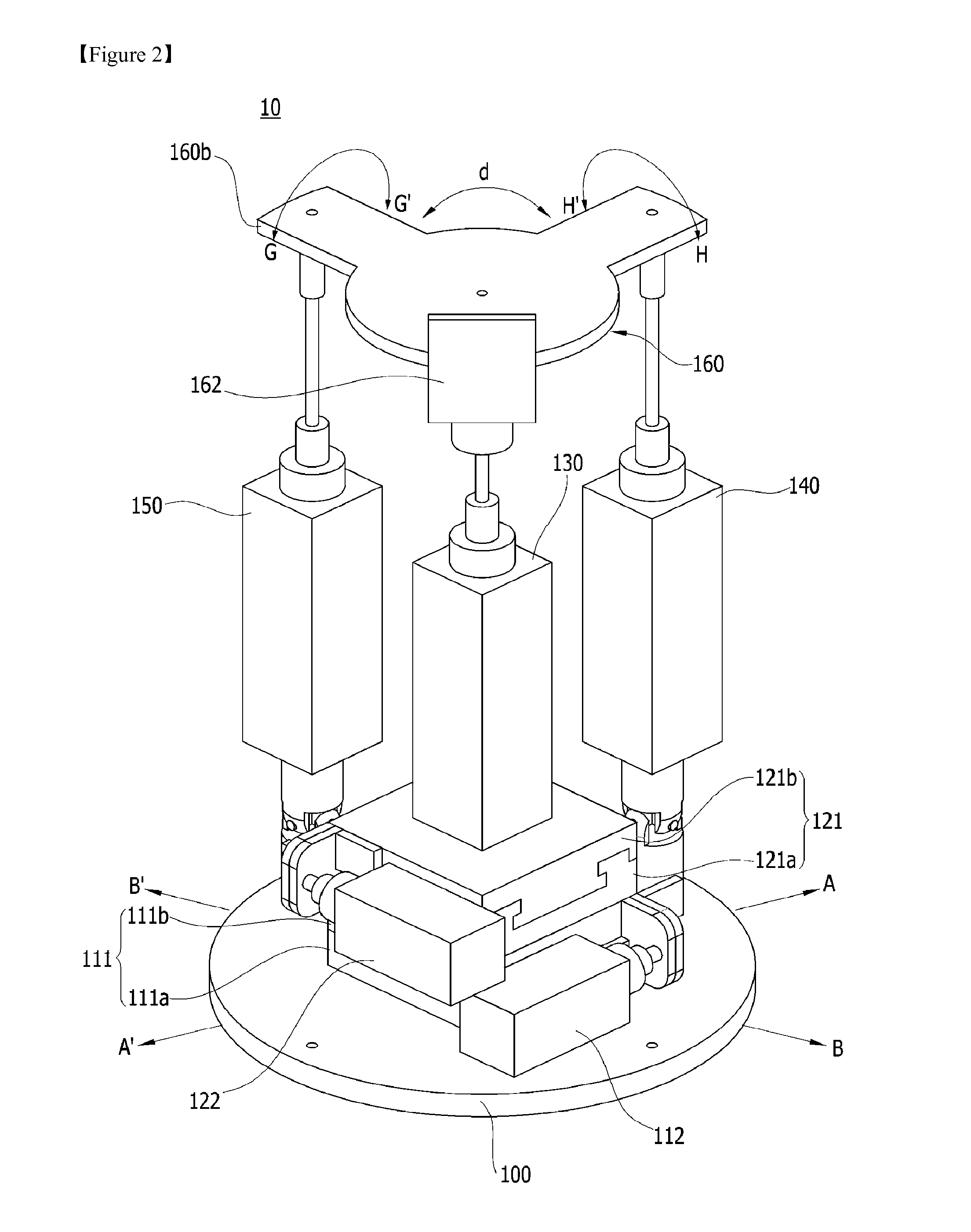
[0036]FIG. 1 is a perspective view of a parallel micro-robot with 5 degrees of freedom according to a first embodiment of the present invention, and FIG. 2 is another perspective view of a parallel micro-robot with 5 degrees of freedom according to a first embodiment of the present invention.

[0037]Referring to FIGS. 1-2, according to a first embodiment of the present invention, a parallel micro-robot with 5 degrees of freedom includes a base plate 100, a first slide moving unit 110, a second slide moving unit 120, an up / down moving actuator 130, a first angle adjusting actuator 140, a second angle adjusting actuator 150, and an operating plate 160.

[0038]The base plate 100 is rotatably coupled to a macro-robot (20: Referring to FIG. 3). For example, the base plate 100 may be formed in a circular form and rotatably coupled to the macro-robot 20.

[0039]The first slide moving unit 110 is installed on the base plate 100. For example, the first slide moving unit 110 includes a LM guide 111...

second embodiment

[0059]FIG. 4 is a perspective view of a parallel micro-robot with 5 degrees of freedom according to a second embodiment of the present invention.

[0060]According to an embodiment of the present invention, a parallel micro-robot with five degrees of freedom is substantially the same as the parallel micro-robot with five degrees of freedom of the first embodiment except for a connection formation of the up / down moving actuator and the addition of a roll motion preventing unit 170, a detailed explanation is skipped except for a connection formation between the base plate 160 and the up / down moving actuator 130 and some of roll motion preventing unit 170, and the same reference numerals are given to the same elements as to the first embodiment.

[0061]Referring to FIG. 4, the operating plate 160 may further comprise a connecting hole 160d in a center portion. Meanwhile, the two shafts rotating connection means that is connected to the up / down moving actuator 130 is inserted and coupled to ...


PUM


Abstract

A parallel micro-robot with five degrees of freedom that is capable of manufacturing in compact size as well as capable of controlling more precisely compared with conventional parallel robot is disclosed. The parallel micro-robot with five degrees of freedom is capable of controlling an angle of the operating plate very precisely around two shafts rotating connection means which couples operating plate and up / down height adjusting actuator using a first and second angle adjusting actuator, and therefore, high accuracy is secured.

Description

TECHNICAL FIELD[0001]Exemplary embodiments of the present invention relate to a micro-robot providing parallel structure and 5 degrees of freedom. More particularly, exemplary embodiments of the present invention relate to a micro-robot providing parallel structure with 5 degrees of freedom used in stereotactic surgery.BACKGROUND ART[0002]In general, conventionally, serial structured robot is used to control a position and an orientation on a three-dimensional during an operation using robot. However, in recent years, various types of robots with parallel structure have been developed and are used alternatively to the serial structure.[0003]The advantage of the parallel surgical robot is that it is possible to increase a speed and an acceleration of a machine by reducing inertial mass of moving part compared to serial surgery robot, to increase rigidity of machine by coupling a base plate and an operating plate with plurality of actuators in which the actuators receive tensile and c...

Claims


Application Information

Patent Timeline
Patent Type & Authority Applications(United States)
IPC IPC(8): B25J7/00B25J9/00
CPCB25J7/00B25J9/0063B25J9/0072Y10T74/20305B25J9/06
Inventor KIM, WHEE-KUKKIM, SUNG-MOKCHUNG, JAE-HEONYI, BYUNG-JU
Owner KOHYOUNG TECH
Learn More