Directional antenna structure with dipole antenna element

a technology of dipole antenna and directional antenna, which is applied in the direction of antennas, antenna feed intermediates, electrical devices, etc., can solve the problems of limited and conventional high-directional antenna structures, and cannot be applied to a variety of small mobile devices, and achieve the effect of enhancing the total gain of the antenna structur

Active Publication Date: 2015-02-12
WISTRON NEWEB
View PDF5 Cites 13 Cited by
  • Summary
  • Abstract
  • Description
  • Claims
  • Application Information

AI Technical Summary

Benefits of technology

[0008]In another exemplary embodiment, the disclosure is directed to an antenna structure, comprising: a first dipole antenna element, transmitting a first electromagnetic signal; and a reflectio

Problems solved by technology

A conventional high directional antenna structure is often limited by a long distance from a radiatio

Method used


Image

  • Directional antenna structure with dipole antenna element
  • Directional antenna structure with dipole antenna element
  • Directional antenna structure with dipole antenna element

Examples


Embodiment Construction

[0021]In order to illustrate the purposes, features and advantages of the invention, the embodiments and figures thereof are shown in detail as follows.

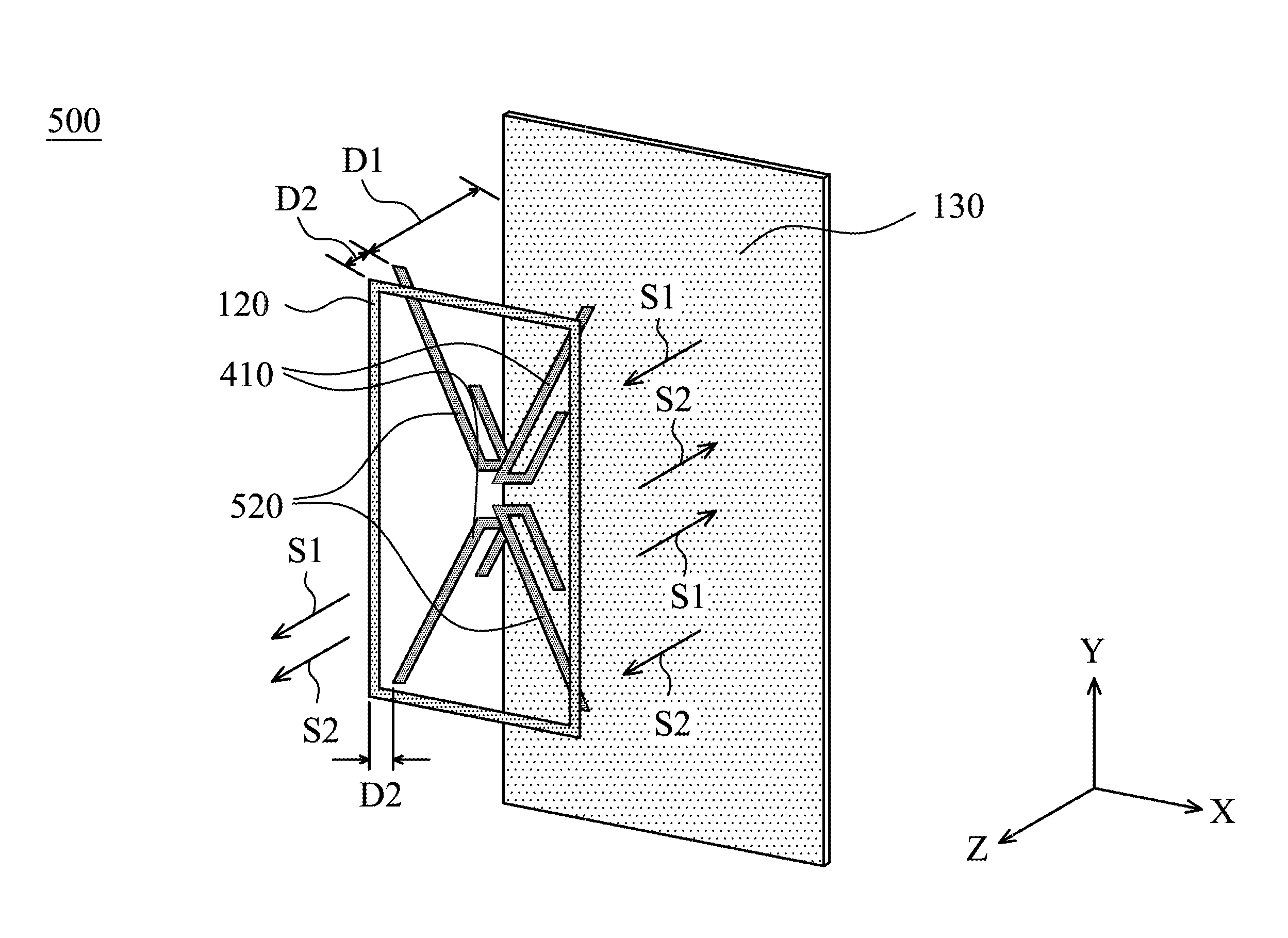
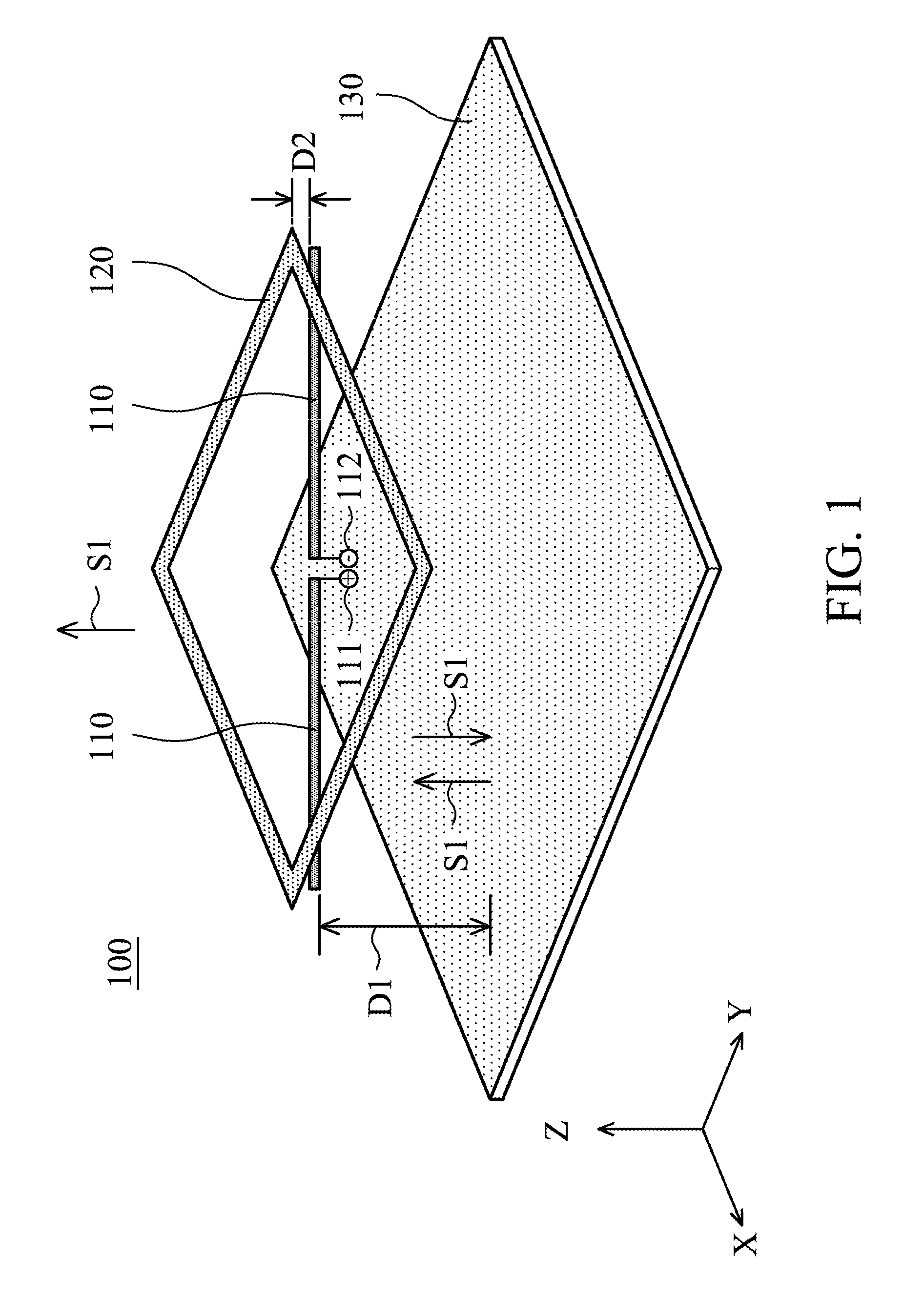
[0022]FIG. 1 is a diagram for illustrating an antenna structure 100 according to an embodiment of the invention. The antenna structure 100 may be disposed in a mobile device, such as a smartphone, a tablet computer, or a notebook computer. Furthermore, the antenna structure 100 may be independently configured as an external antenna module, and the external antenna module may be coupled to an electronic device. The antenna structure 100 may be further coupled to a communication module of the mobile device or the electronic device to provide the function of wireless communication. As shown in FIG. 1, the antenna structure 100 at least comprises a first dipole antenna element 110, a closed-loop conductor 120, and a reflection plane 130. The first dipole antenna element 110 may comprise two radiation conductors extending in opposite dire...


PUM


Abstract

An antenna structure includes a dipole antenna element, a closed-loop conductor, and a reflection plane. The dipole antenna element is configured to transmit an electromagnetic signal. The closed-loop conductor is disposed adjacent to the dipole antenna element. The dipole antenna element is substantially between the closed-loop conductor and the reflection plane, or the closed-loop conductor is substantially between the dipole antenna element and the reflection plane. The reflection plane is configured to reflect the electromagnetic signal from the dipole antenna element so as to enhance the total gain of the antenna structure. The mutual coupling effect between the closed-loop conductor and the dipole antenna element effectively causes the distance between the dipole antenna element and the reflection plane to be shorter.

Description

CROSS REFERENCE TO RELATED APPLICATIONS[0001]This application claims priority of Taiwan Patent Application No. 102128593 filed on Aug. 9, 2013, the entirety of which is incorporated by reference herein.BACKGROUND OF THE INVENTION[0002]1. Field of the Invention[0003]The disclosure generally relates to an antenna structure, and more particularly, to a directional antenna structure with a dipole antenna element.[0004]2. Description of the Related Art[0005]With the progress of mobile communication technology, portable electronic devices, such as portable computers, mobile phones, tablet computers, multimedia players, and other hybrid functional mobile devices, have become more common. To satisfy user demand, portable electronic devices can usually perform wireless communication functions. Some functions cover a large wireless communication area, for example, mobile phones using 2G, 3G, and LTE (Long Term Evolution) systems and using frequency bands of 700 MHz, 850 MHz, 900 MHz, 1800 MHz...

Claims


Application Information

Patent Timeline
IPC IPC(8): H01Q5/00H01Q9/16
CPCH01Q9/16H01Q5/0062H01Q1/36H01Q9/28H01Q19/108
Inventor CHENG, CHIA-SHANG
Owner WISTRON NEWEB
Why Eureka
Try Eureka