Blower fan and electronic device

a technology of blower fan and electronic device, which is applied in the direction of electric apparatus casing/cabinet/drawer, piston pump, instruments, etc., can solve the problems of difficult to reduce the size of the outer-rotor type blower fan, the increase in the temperature inside the electronic device may not be negligible, and the increase in the generation of heat in the electronic device. , to achieve the effect of reducing the thickness of the blower fan and sufficient air volum

Inactive Publication Date: 2015-02-12
NIDEC CORP
View PDF4 Cites 8 Cited by
  • Summary
  • Abstract
  • Description
  • Claims
  • Application Information

AI Technical Summary

Benefits of technology

[0009]The present invention makes it possible to secure a sufficient air volume while achieving a reduction in the thickness of a blower fan.

Problems solved by technology

In addition, such electronic devices have been becoming more and more sophisticated in functionality, causing a considerable increase in generation of heat in the electronic devices.
Therefore, even in the case where components inside such an electronic device do not generate much heat, an increase in a temperature inside the electronic device may not be negligible.
A blower fan of the outer-rotor type has a large rotating portion, and it is difficult to reduce the size of the blower fan of the outer-rotor type.
However, a stator portion of the blower fan of the inner-rotor type is arranged at a relatively high axial position, and this makes it difficult to reduce the thickness of the blower fan of the inner-rotor type.
As a result, it is difficult to secure a sufficient air volume while achieving a reduction in the thickness of the blower fan of the inner-rotor type.

Method used


Image

  • Blower fan and electronic device
  • Blower fan and electronic device
  • Blower fan and electronic device

Examples


Embodiment Construction

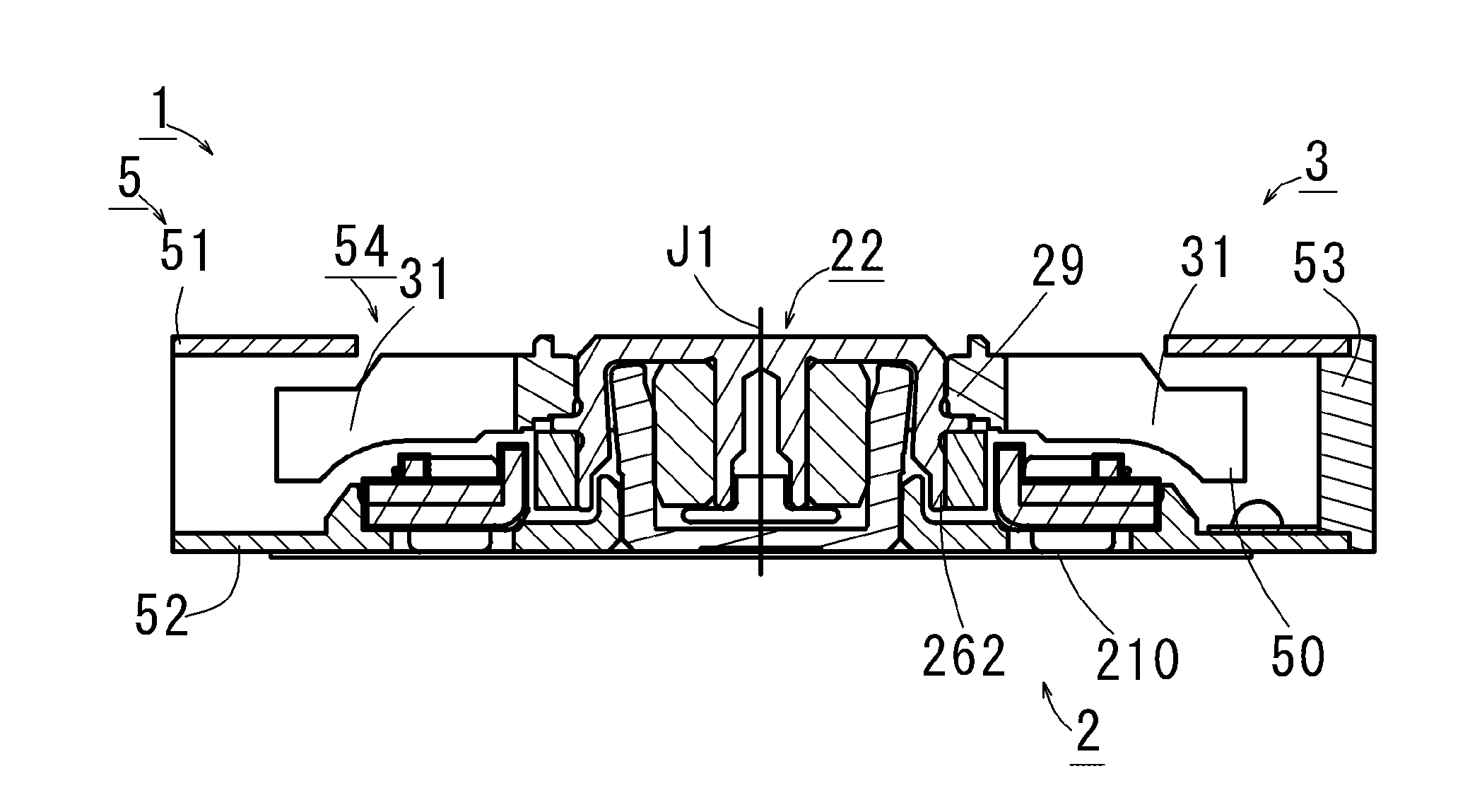
[0023]It is assumed herein that an upper side and a lower side in a direction parallel to a central axis J1 of a blower fan 1 illustrated in FIG. 1 are referred to simply as an upper side and a lower side, respectively. Note that a vertical direction assumed herein may not necessarily correspond with a vertical direction of the blower fan 1 when the blower fan 1 is actually installed in a device. It is also assumed herein that a circumferential direction about the central axis J1 is simply referred to by the term “circumferential direction”, “circumferential”, or “circumferentially”, that radial directions centered on the central axis J1 are simply referred to by the term “radial direction”, “radial”, or “radially”, and that the direction parallel to the central axis J1 is simply referred to by the term “axial direction”, “axial”, or “axially”.

[0024]FIG. 1 is a vertical cross-sectional view of the blower fan 1 according to a first preferred embodiment of the present invention. The b...


PUM


Abstract

A blower fan according to a preferred embodiment of the present invention is a centrifugal fan including a stationary portion, a bearing mechanism, and a rotating portion. The stationary portion includes a lower plate portion and a stator. The stator includes a plurality of teeth each of which has a radially inner end including an upward projecting portion arranged to extend axially upward.

Description

BACKGROUND OF THE INVENTION[0001]1. Field of the Invention[0002]The present invention relates to a blower fan of an inner-rotor type.[0003]2. Description of the Related Art[0004]In recent years, electronic devices, such as notebook personal computers and tablet personal computers, have been becoming thinner and thinner. In addition, such electronic devices have been becoming more and more sophisticated in functionality, causing a considerable increase in generation of heat in the electronic devices. Inside such slim electronic devices, a large number of electronic components are arranged, and a space occupied by an air is not large. Therefore, even in the case where components inside such an electronic device do not generate much heat, an increase in a temperature inside the electronic device may not be negligible. Accordingly, a blower fan is arranged in the electronic device with the view of cooling an interior of the electronic device.[0005]In a slim electronic device, a slim cen...

Claims


Application Information

Patent Timeline
Patent Type & Authority Applications(United States)
IPC IPC(8): F04D25/06G06F1/20
CPCG06F1/203F04D25/0613F04D25/0606F04D29/063F04D29/4226F04D25/082F04D29/5806G06F1/206
Inventor HIRANO, HIROAKITAMAOKA, TAKEHITO
Owner NIDEC CORP
Why Eureka
Try Eureka