
Method and wireless communication device for using an antenna as a sensor device in guiding selection of optimized tuning networks

a wireless communication device and antenna technology, applied in the field of wireless communication devices, can solve the problems of mismatch loss, affecting the efficiency performance of antenna systems, and prone to de-tuning effects of antennas

Active Publication Date: 2015-02-12
GOOGLE TECH HLDG LLC
View PDF10 Cites 267 Cited by
  • Summary
  • Abstract
  • Description
  • Claims
  • Application Information

AI Technical Summary

Benefits of technology

The patent text describes a method and system for tuning antennas in wireless communication devices using detected changes in antenna self-capacitance. The system includes multiple antenna elements and a modem that detects changes in antenna self-capacitance and uses pre-established mapping of antenna self-capacitance to determine the appropriate tuning states for each antenna element. The system can change the tuning states of multiple tunable matching circuits and perform antenna tuning using detected real-time changes in antenna self-capacitance and pre-established mappings of antenna self-capacitance and antenna tuning states. The technical effect of this patent is to provide a more efficient and effective method for tuning antennas in wireless communication devices, allowing for better performance and reliability in challenging conditions.

Problems solved by technology

An increased antenna Q most likely indicates a narrowband antenna and causes the antenna to be more susceptible to de-tuning effects which occur when the corresponding wireless communication device is held within a user's hand or against the body, when compared to traditional antenna designs.
De-tuning in a high Q antenna increases mismatch losses due to reflection and, as a result, the antenna system efficiency performance is negatively impacted.

Method used


Image

  • Method and wireless communication device for using an antenna as a sensor device in guiding selection of optimized tuning networks
  • Method and wireless communication device for using an antenna as a sensor device in guiding selection of optimized tuning networks
  • Method and wireless communication device for using an antenna as a sensor device in guiding selection of optimized tuning networks

Examples


Embodiment Construction

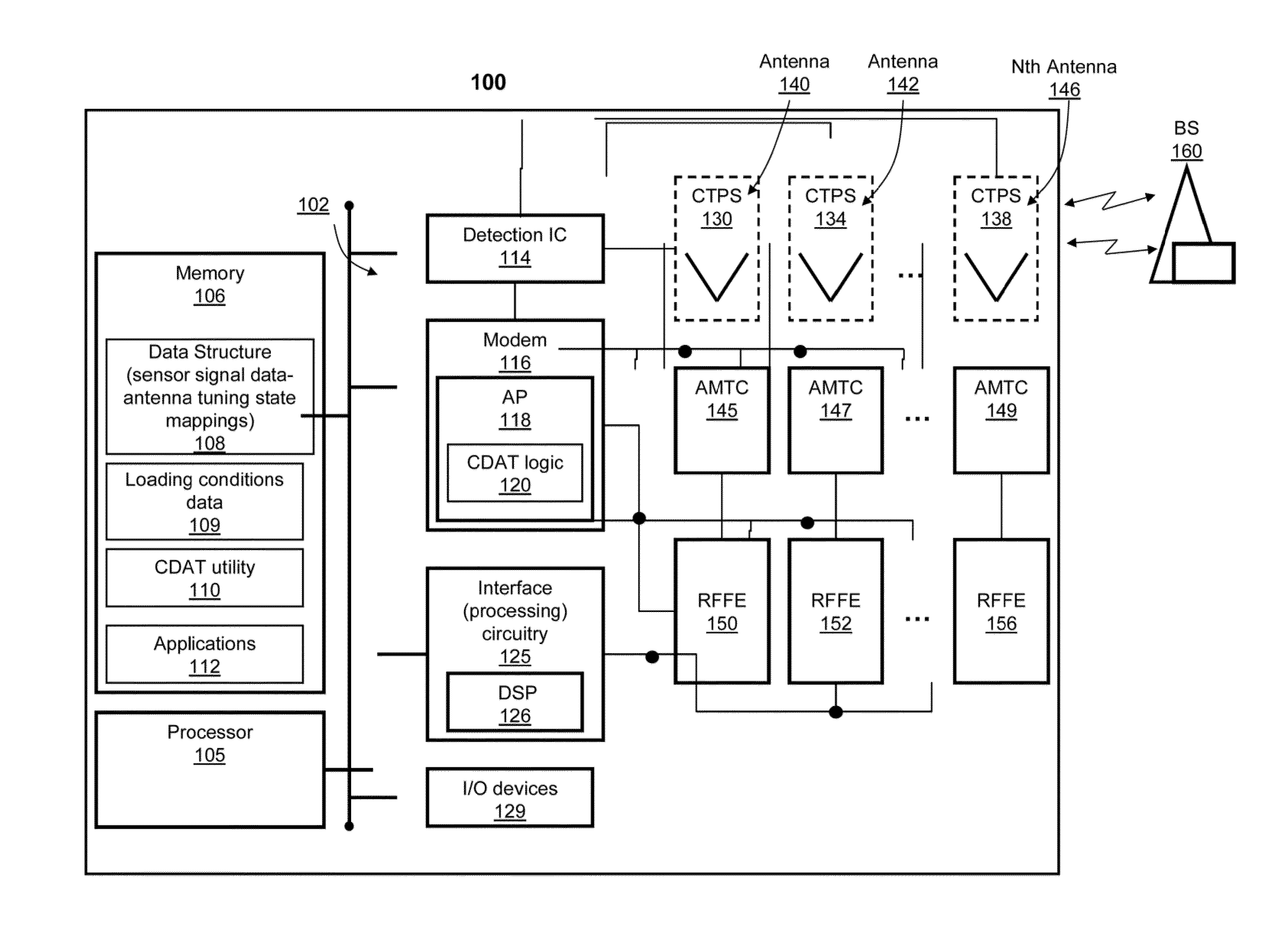
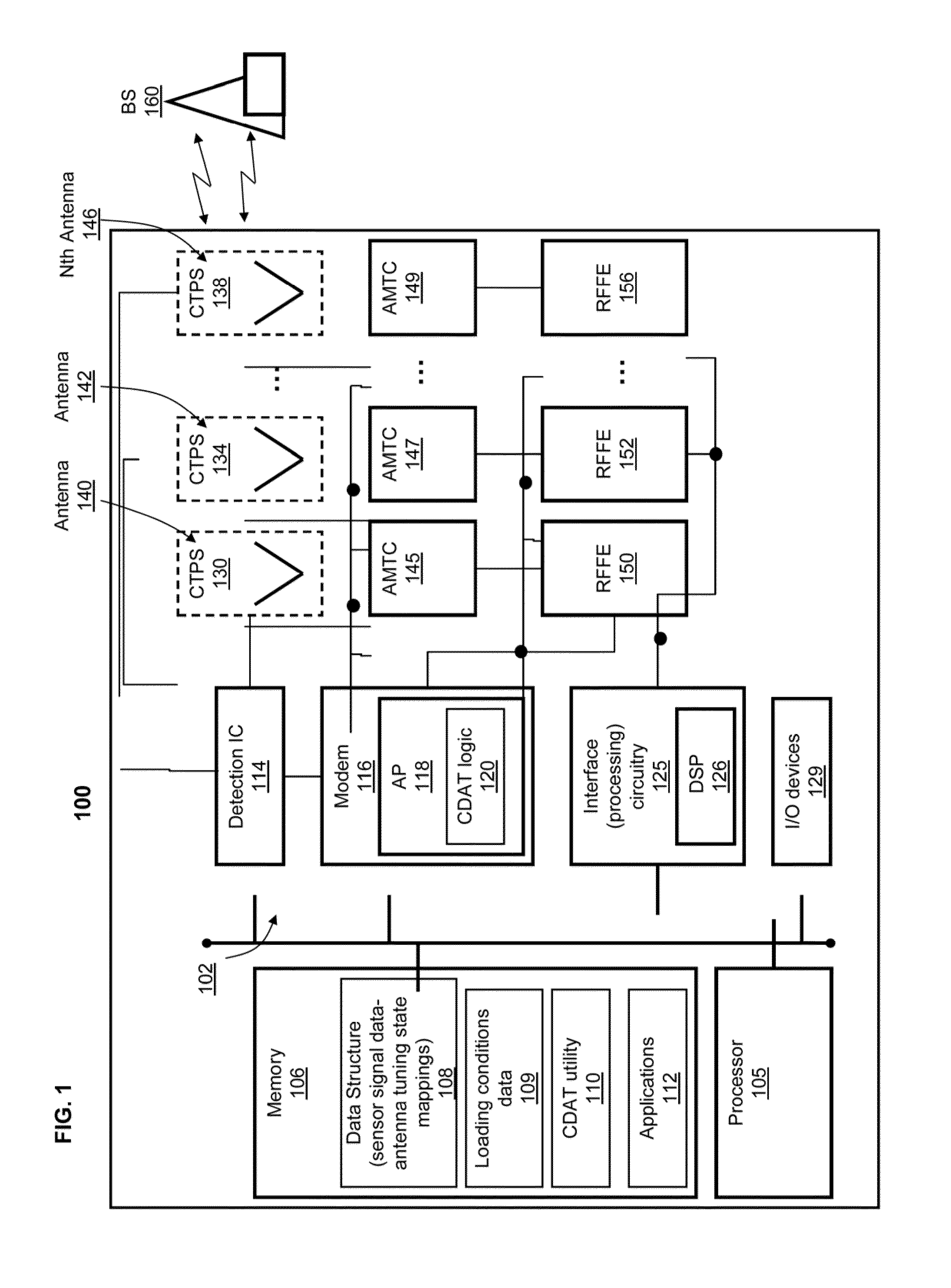
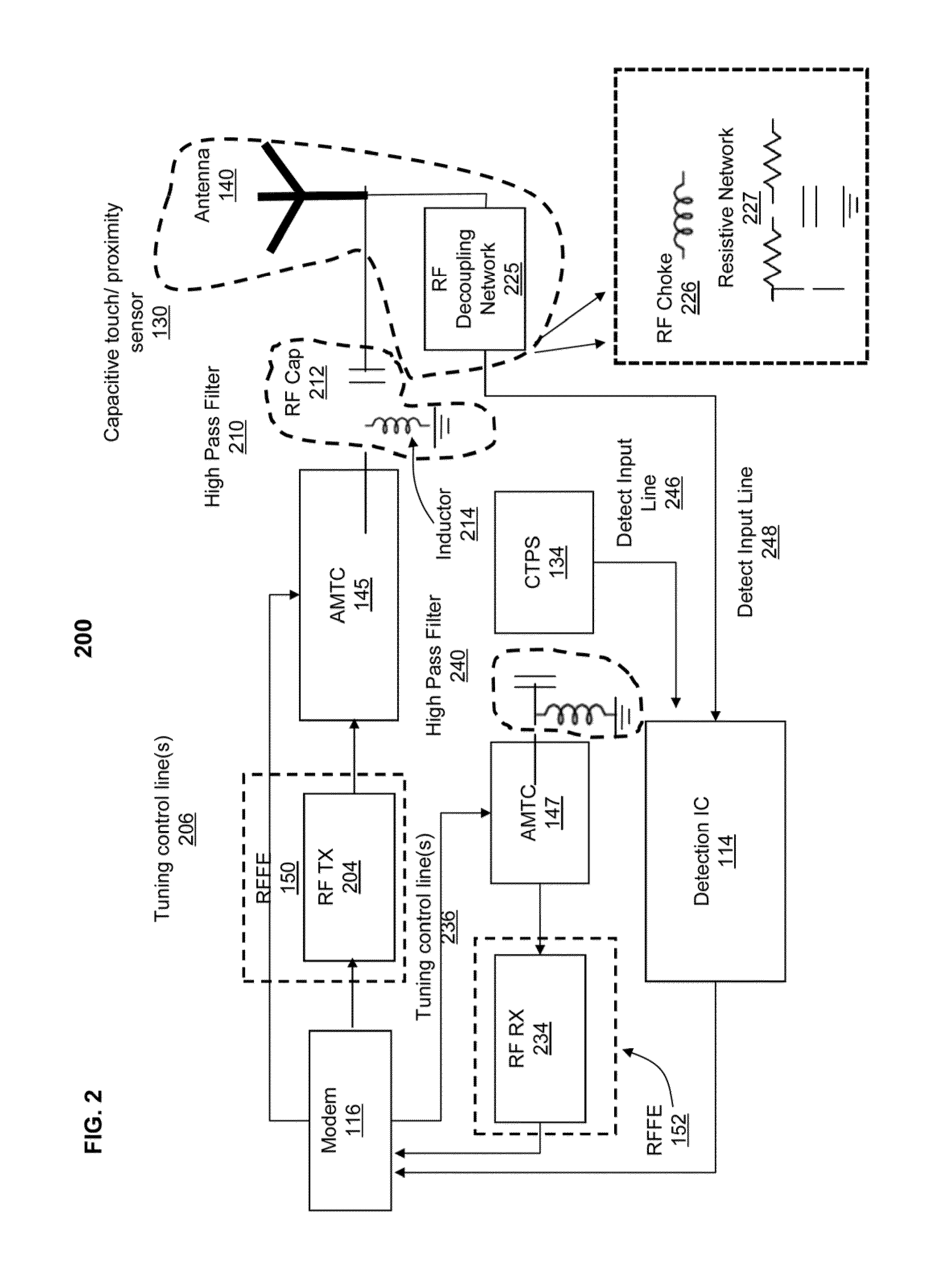
[0014]The illustrative embodiments provide a method and system for performing antenna tuning using detected changes in antenna self-capacitance in a wireless communication device. A modem detects changes in antenna self-capacitance by utilizing multiple antenna elements. The modem determines a current antenna loading condition using the detected changes in antenna self-capacitance. The modem determines appropriate tuning states for each antenna matching and tuning circuit (AMTC) associated with a respective antenna element. In order to determine the appropriate tuning states, the modem utilizes pre-established antenna self-capacitance information which is mapped to antenna tuning states. The antenna tuning states which are respectively mapped to pre-established antenna self-capacitance are empirically pre-determined by correlating antenna self-capacitance changes to antenna impedance changes. The modem is thus able to change the tuning states of multiple tunable matching circuits an...


PUM


Abstract

A method and system performs antenna tuning using detected changes in antenna self-capacitance in a wireless communication device. A modem detects changes in antenna self-capacitance by utilizing multiple antenna elements. The modem determines a current antenna loading condition using the detected changes in antenna self-capacitance. The modem determines appropriate tuning states for each antenna matching and tuning circuit (AMTC) associated with a respective antenna element. In order to determine the appropriate tuning states, the modem utilizes pre-established antenna self-capacitance information which is mapped to antenna tuning states. The antenna tuning states which are respectively mapped to pre-established antenna self-capacitance are empirically pre-determined by correlating antenna self-capacitance changes to antenna impedance changes. The modem is thus able to change the tuning states of multiple tunable matching circuits and perform antenna tuning using (a) detected real-time changes in antenna self-capacitance and (b) pre-established mappings of antenna self-capacitance and antenna tuning states.

Description

BACKGROUND[0001]1. Technical Field[0002]The present disclosure relates in general to wireless communication devices and in particular to antenna tuning in wireless communication devices.[0003]2. Description of the Related Art[0004]The evolution of multi-band, multi-mode wireless communication technologies (e.g., Long Term Evolution (LTE), code division multiple access (CDMA) 1x, Evolution Data Optimized (EVDO), Universal Mobile Telecommunications System (UMTS) and Global System for Mobile Communications (GSM)) combined with a need for aggressive, unique and attractive design features and characteristics, such as borderless display for user equipment, has led to increasing demands for innovative antenna designs in which antennas utilize a much smaller space or “keep out” within the user equipment.[0005]A more compact antenna design, which utilizes less space within the user equipment, increases the antenna q factor (Q) (i.e., more localized energy near the antenna). An increased ante...

Claims


Application Information

Patent Timeline
Patent Type & Authority Applications(United States)
IPC IPC(8): H04B7/04
CPCH04B7/0404H01Q1/243H01Q1/44H03K17/955
Inventor RAMASAMY, SURESH K.BLACK, GREGORY R.DIETRICH, AARON L.LEIZEROVICH, GUSTAVO D.MINASI, DAVID H.SHEE, KOON K.
Owner GOOGLE TECH HLDG LLC
Learn More