Valved enteral administration assembly

a technology of enteral and valve, which is applied in the direction of intravenous devices, medical devices, medical devices, etc., can solve the problems that the medication cannot be delivered into the port with a luer tapered syringe, and achieve the effects of reducing the accumulation of residues and biofilms, facilitating fluid transmission, and reducing the settle of suspended particles

Active Publication Date: 2015-02-12
HOSPI CORP
View PDF5 Cites 32 Cited by
  • Summary
  • Abstract
  • Description
  • Claims
  • Application Information

AI Technical Summary

Benefits of technology

[0027]In further embodiments, the enteral port optimizes safe and effective administration of medication to the gastro-intestinal tract. This can be accomplished in several ways. For example, in any of the preceding embodiments, the port mates only with an enteral tapered syringe or enteral connector and is not adaptable to a Luer tapered syringe or connectors. In further embodiments, the port is designed to be permanently placed on the enteral device in a readily manufacturable manner.
[0028]Additionally, in any of the preceding embodiments, medication cannot be delivered into the port with a Luer tapered syringe. In further embodiments, the port is able to produce and maintain turbulent flow to decrease settling of suspended particles and decrease the buildup of residue and biofilm formation on the walls of the valve. In additional embodiments, the port and its valve do not clog when substances such as both small and large particulate suspensions, and thicker more viscous substances such as oils, emulsions are injected through the device. In any of the preceding embodiments, the port valve is configured to avoid getting lodged open with suspended medications or particles which would allow for possible leakage of fluids.
[0029]Furthermore, in any of the preceding embodiments, the port valve can be configured for one way delivery only, to avoid medication dose or bio-hazardous material from being inadvertently extracted from the device. However, alternative embodiments provide for bi-directional flow.
[0030]In another aspect, the embodiments described provide for an enteral fluid delivery device having a turbulent flow valve assembly or mecha

Problems solved by technology

For example, in any of the preceding embodiments, the port mates only with an enteral tapered syringe or enteral connector and is not adaptable to a Luer

Method used


Image

  • Valved enteral administration assembly
  • Valved enteral administration assembly
  • Valved enteral administration assembly

Examples


Embodiment Construction

[0079]The following description and drawings are illustrative and are not to be construed as limiting. Numerous specific details are described to provide a thorough understanding. However, in certain instances, well known or conventional details may not be described in order to avoid obscuring the description.

[0080]The term “about” when used before a numerical designation, e.g., length, width, dimension, or ranges, indicates approximations which may vary by (+) or (−) 1%.

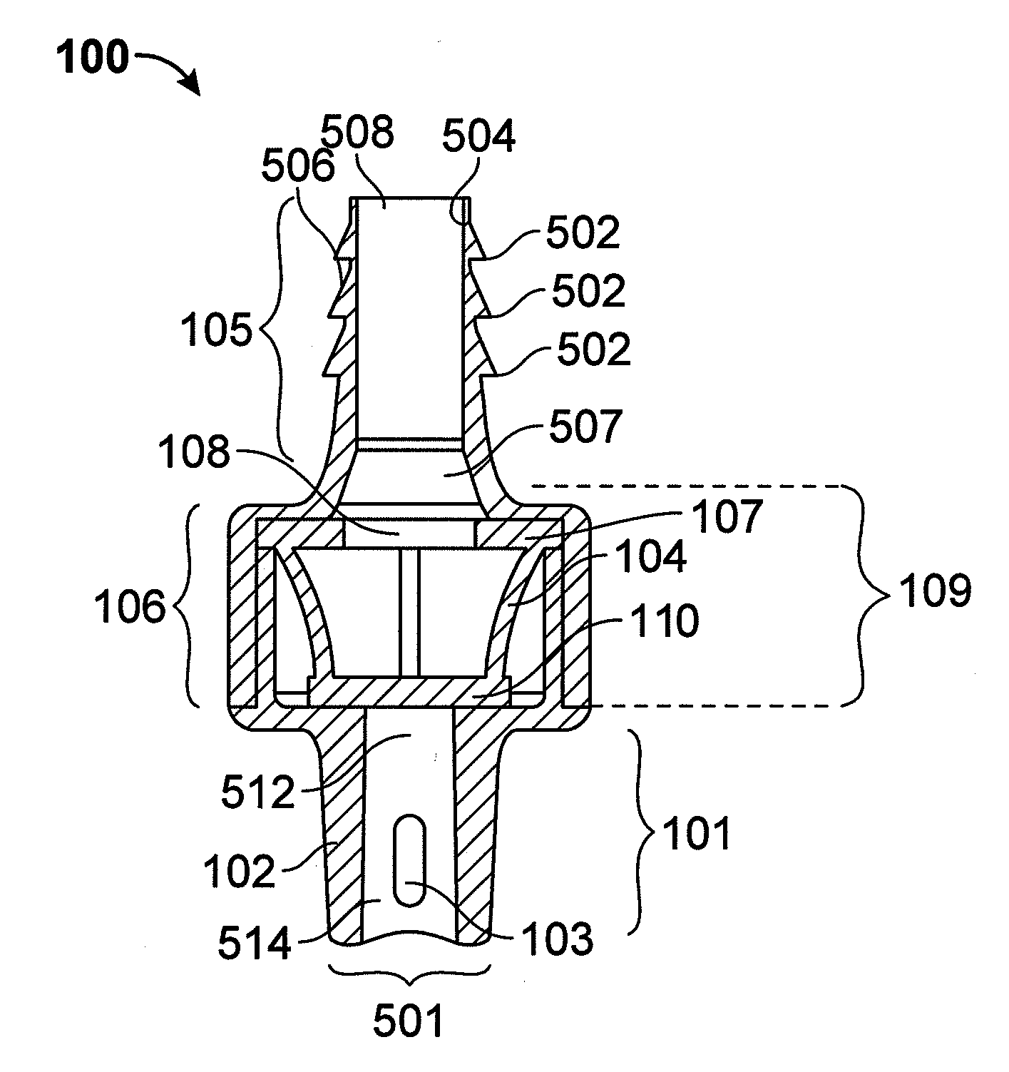
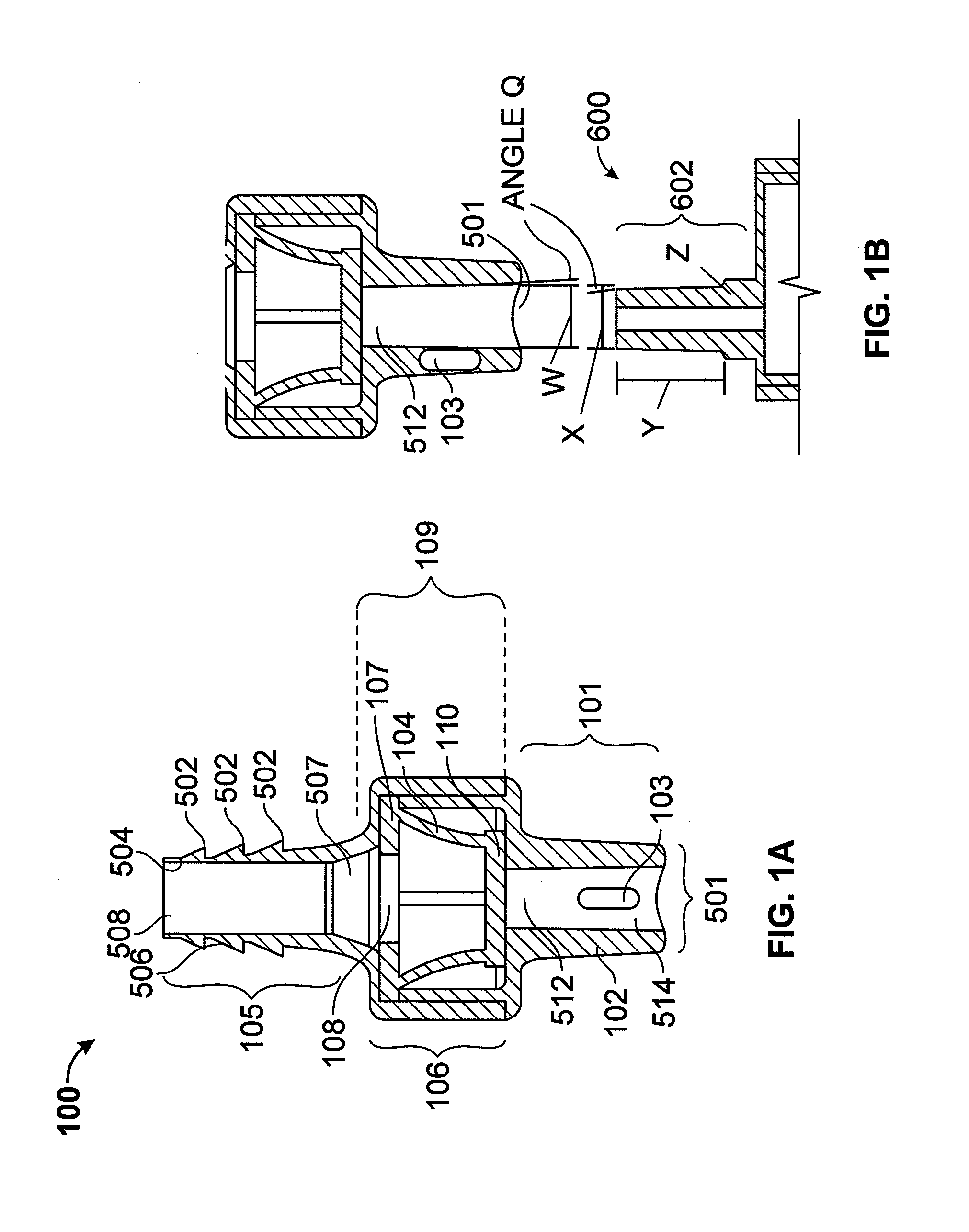
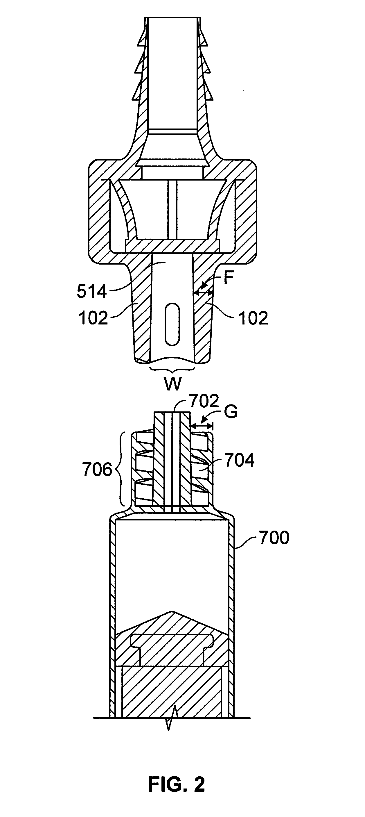
[0081]As discussed above, one of the challenges for enteral patient care has been the significant risk of accidently introducing enteral targeted medication or other substances through non-enteral ports into the patient. Because currently available administration ports are designed to be non-restrictively compatible with a variety of fluid delivery devices such as luer-type or enteral-type syringes, these administration ports do not mitigate against the misadministration of medication. To address this need, novel an...


PUM


Abstract

An enteral administration assembly for administering fluids through an enteral device. The administration assembly comprising an inlet, an outlet, and a valve mechanism between the inlet and outlet. The inlet is configured to interlock with only an enteral device to form a sealed connection allowing the passage of fluid between the enteral device and the inlet. The assembly may include a valve or turbulating mechanism comprising a valve and at least one turbulator adapted to change the direction of fluid flowing through the assembly to prevent clogging and flocculation of administered substances.

Description

CROSS REFERENCE TO RELATED APPLICATIONS[0001]This application claims priority to U.S. Provisional Patent Application No. 61 / 632,876, filed on Feb. 1, 2012, titled “TURBULENT FLOW VALVE AN APPARATUS AND METHOD FOR CREATING TURBULENT FLUID FLOW WITHIN AN ENCLOSED SPACE,” which is herein incorporated by reference in its entirety. This application may be related to U.S. application Ser. No. 12 / 235,601, filed on Sep. 23, 2008, titled APPARATUSES AND METHODS FOR MEDICATION ADMINISTRATION, which is herein incorporated by reference in its entirety.INCORPORATION BY REFERENCE[0002]All publications and patent applications mentioned in this specification are herein incorporated by reference to the same extent as if each individual publication or patent application was specifically and individually indicated to be incorporated by reference.FIELD[0003]This invention relates generally to methods, systems, and apparatuses for the enteral delivery of medications to patients. More particularly, embod...

Claims


Application Information

Patent Timeline
IPC IPC(8): A61M39/16A61J7/00A61J15/00A61M39/10
CPCA61M39/16A61J15/0092A61J7/0053A61M39/1011A61M39/26A61M31/00A61M2206/14A61M2210/1067
Inventor MACY, JR., BRADFORDLADABAUM, IGALEATON, JOHN
Owner HOSPI CORP
Why Eureka
Try Eureka