
Frequency doubling antenna sensor for wireless strain and crack sensing

a wireless strain and crack sensing and frequency doubling technology, applied in the field of strain and crack sensors, can solve the problems of increasing installation time and system cost, inconvenient for many practical applications, and limited distance achieved by inductive coupling

Active Publication Date: 2015-02-19
GEORGIA TECH RES CORP
View PDF7 Cites 10 Cited by
  • Summary
  • Abstract
  • Description
  • Claims
  • Application Information

AI Technical Summary

Benefits of technology

The present invention is a strain and crack sensor for sensing an amount of strain or cracks in an object. It uses a receiving planar antenna and a transmitting planar antenna bonded to the object, which detect changes in resonant frequency caused by strain or cracks. A matching element is used to cause the transmitting planar antenna to radiate a response signal. The sensor system also includes a sensing unit that detects the response signal frequency and calculates the amount of strain induced in the object. The invention allows for the non-destructive and accurate detection of strain and cracks in objects.

Problems solved by technology

However, when applied to large structures, traditional metal foil strain gages require lengthy cable connections for power and data acquisition, which can significantly increase installation time and system cost.
However, the interrogation distance achieved by inductive coupling is usually limited to several inches, which is inconvenient for many practical applications.
However, the light-switching mechanism is not practical for outdoor application, where light intensity is usually so strong that the phototransistor is constantly activated and thus, loses the ability to switch.

Method used


Image

  • Frequency doubling antenna sensor for wireless strain and crack sensing
  • Frequency doubling antenna sensor for wireless strain and crack sensing
  • Frequency doubling antenna sensor for wireless strain and crack sensing

Examples


Embodiment Construction

[0020]A preferred embodiment of the invention is now described in detail. Referring to the drawings, like numbers indicate like parts throughout the views. Unless otherwise specifically indicated in the disclosure that follows, the drawings are not necessarily drawn to scale. As used in the description herein and throughout the claims, the following terms take the meanings explicitly associated herein, unless the context clearly dictates otherwise: the meaning of “a,”“an,” and “the” includes plural reference, the meaning of “in” includes “in” and “on.”

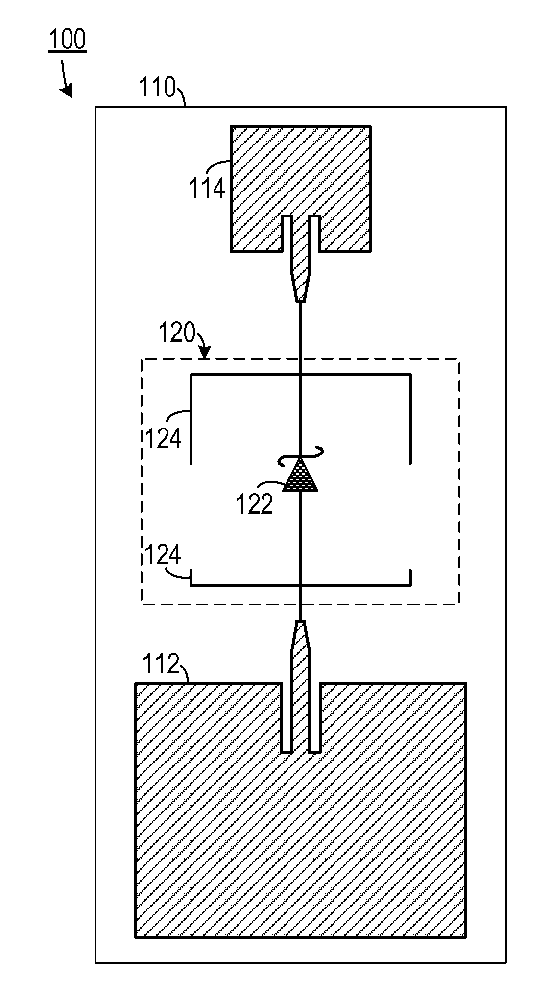
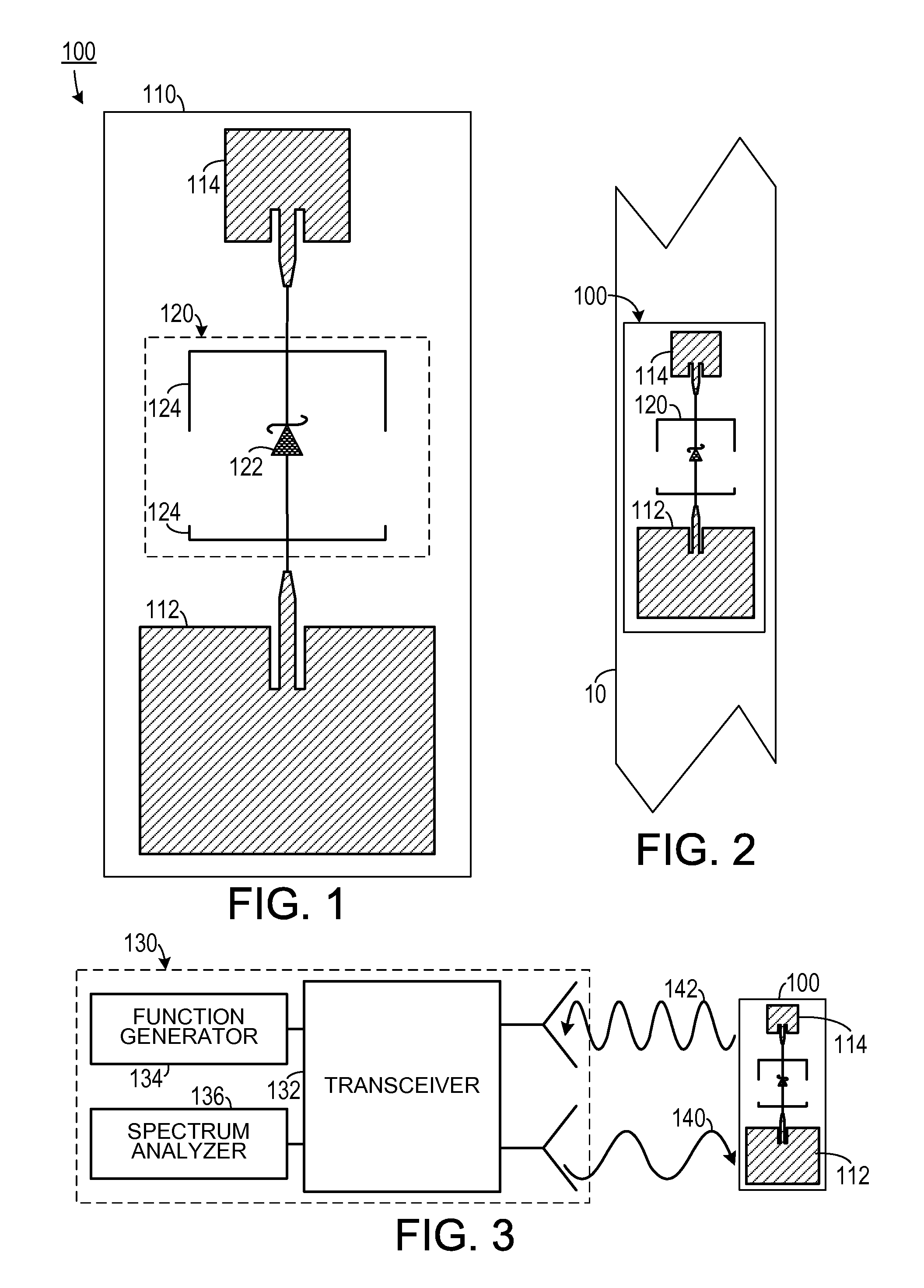
[0021]As shown in FIGS. 1-3, one embodiment of a strain and crack sensor 100 includes a thin dielectric substrate 110, a receiving patch antenna 112 having a first resonant frequency disposed on the substrate, a transmitting patch antenna 114 also disposed on the substrate and having a second resonant frequency that is twice the first resonant frequency. A matching network 120 electrically couples the receiving patch antenna 112 to the...


PUM

PropertyMeasurementUnit
frequencyaaaaaaaaaa
resonance frequencyaaaaaaaaaa

Abstract

A strain and crack sensor senses an amount of strain induced in an object. A receiving planar antenna has a first resonant frequency and is configured to receive a querying signal at the first resonant frequency. A transmitting planar antenna has a second resonant frequency that is twice the first resonant frequency. At least one of the receiving planar antenna and the transmitting planar antenna is bonded to the object so that at least one of strain induced in the object or a crack formed in the object causes a shift in at least one of the first resonant frequency or the second resonant frequency. A matching element is in electrical communication with the first planar antenna and the second planar antenna. The matching element is configured to cause the transmitting planar antenna to radiate a response signal in response to the querying signal.

Description

CROSS-REFERENCE TO RELATED APPLICATION(S)[0001]This application claims the benefit of U.S. Provisional Patent Application Ser. No. 61 / 865,371, filed Aug. 13, 2013, the entirety of which is hereby incorporated herein by reference.STATEMENT OF GOVERNMENT INTEREST[0002]This invention was made with government support under agreement No. DTFH61-10-H-00004, awarded by the DOT, Federal Highway Administration. The government has certain rights in the invention.BACKGROUND OF THE INVENTION[0003]1. Field of the Invention[0004]The present invention relates to strain and crack sensors and, more specifically, to a wireless passive strain and crack sensing systems.[0005]2. Description of the Related Art[0006]In order to accurately assess deterioration of civil, mechanical, and aerospace structures, there has been a large volume of research in structural health monitoring (SHM) over past few decades. Sensors can be used to measure various structural responses and operating conditions, including: st...

Claims


Application Information

Patent Timeline
Patent Type & Authority Applications(United States)
IPC IPC(8): G01L1/00G01N3/02
CPCG01N3/02G01L1/005G01M5/0033G01M5/0083
Inventor YI, XIAOHUACHO, CHUNHEECOOK, BENJAMINWANG, YANGTENTZERIS, MANOSLEON, ROBERTO T.
Owner GEORGIA TECH RES CORP
Learn More