
Breathing Apparatus and Method of Use

a breathing apparatus and breathing technology, applied in the direction of mechanical equipment, respirator, operating means/releasing devices, etc., can solve the problems of affecting the use of oxygen, affecting the oxygen supply of users, and putting users in danger of lacking breathable oxygen

Active Publication Date: 2015-02-19
DRAEGER MEDICAL SYST INC
View PDF5 Cites 3 Cited by
  • Summary
  • Abstract
  • Description
  • Claims
  • Application Information

AI Technical Summary

Benefits of technology

The patent text describes a pneumatic valve assembly that connects a source of compressed air with a lung demand valve. The assembly includes a pressure reducer, a pneumatic valve, and a solenoid valve. The solenoid valve prevents air from flowing from the inlet to the outlet when it is closed and allows air to flow when it is open. The patent also describes a method of configuring a mask for use with the breathing apparatus between a negative pressure mode and a positive pressure mode.

Problems solved by technology

There are many environments where air quality is insufficient for respiration due to insufficient oxygen concentration and / or contamination by unsafe particulate or gaseous matter.
This may occur, for example, during a military operation where adversaries release a toxic or otherwise unsafe gas to prevent capture.
A drawback associated with the SCBA apparatus is the storage capacity of the cylinder retaining compressed air.
These cylinders have a finite capacity and, in environments of high stress, respiration increases thereby depleting the compressed air at a higher rate and potentially placing the user in danger of lacking breathable oxygen.
While different filters can protect against different contaminates in the air, these filters cannot protect a user from oxygen deficiency in the air.
However, a drawback associated with this type of apparatus is the apparatus must be manually switched from a negative pressure state to a positive pressure state.
Since a user needing to make the switch is likely in a compromising and difficult setting, any time delay associated with switching sources of air to a mask could have severe consequences for the user wearing the apparatus as well as those the user is charged with protecting.

Method used


Image

  • Breathing Apparatus and Method of Use
  • Breathing Apparatus and Method of Use
  • Breathing Apparatus and Method of Use

Examples


Embodiment Construction

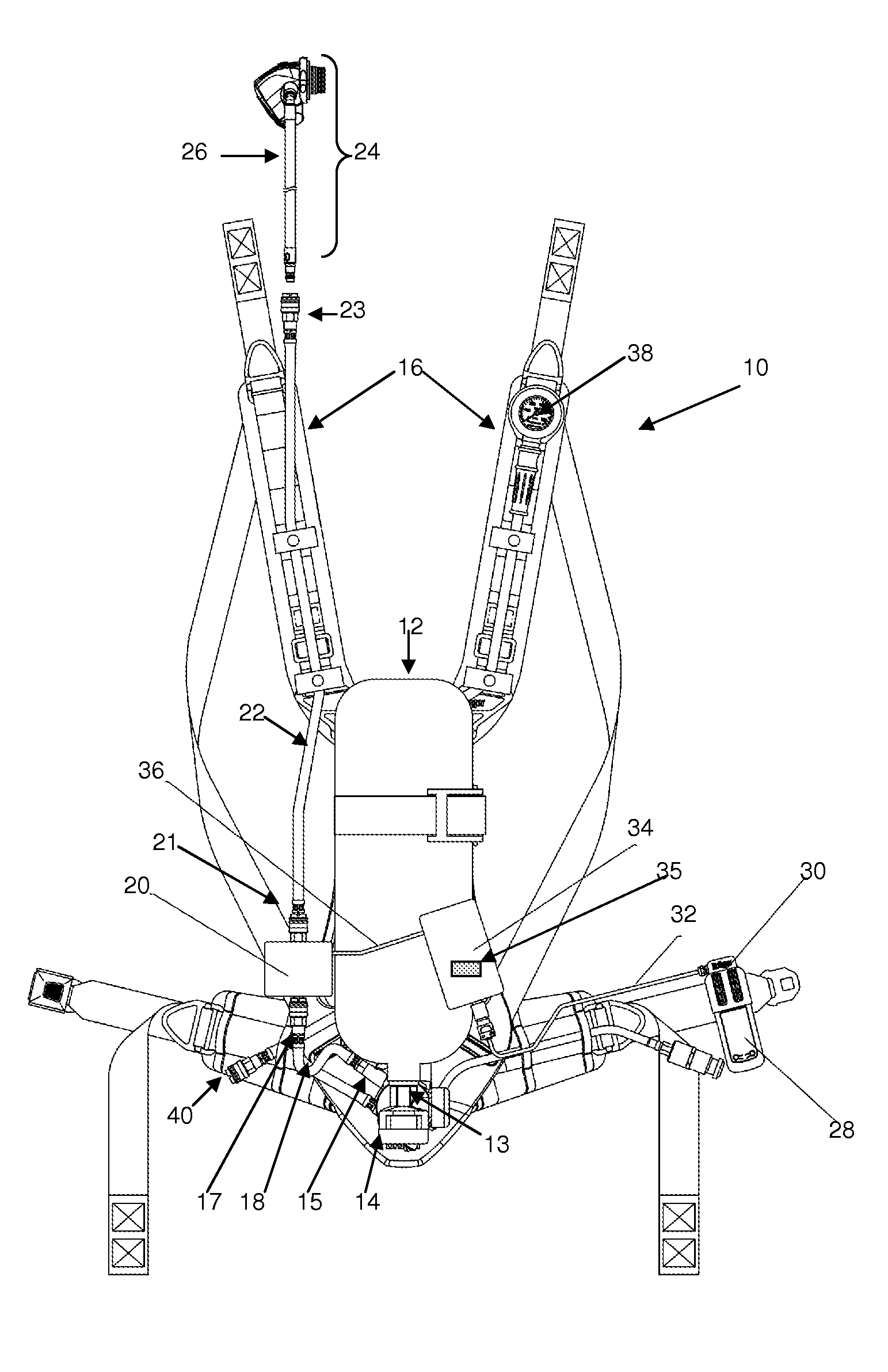
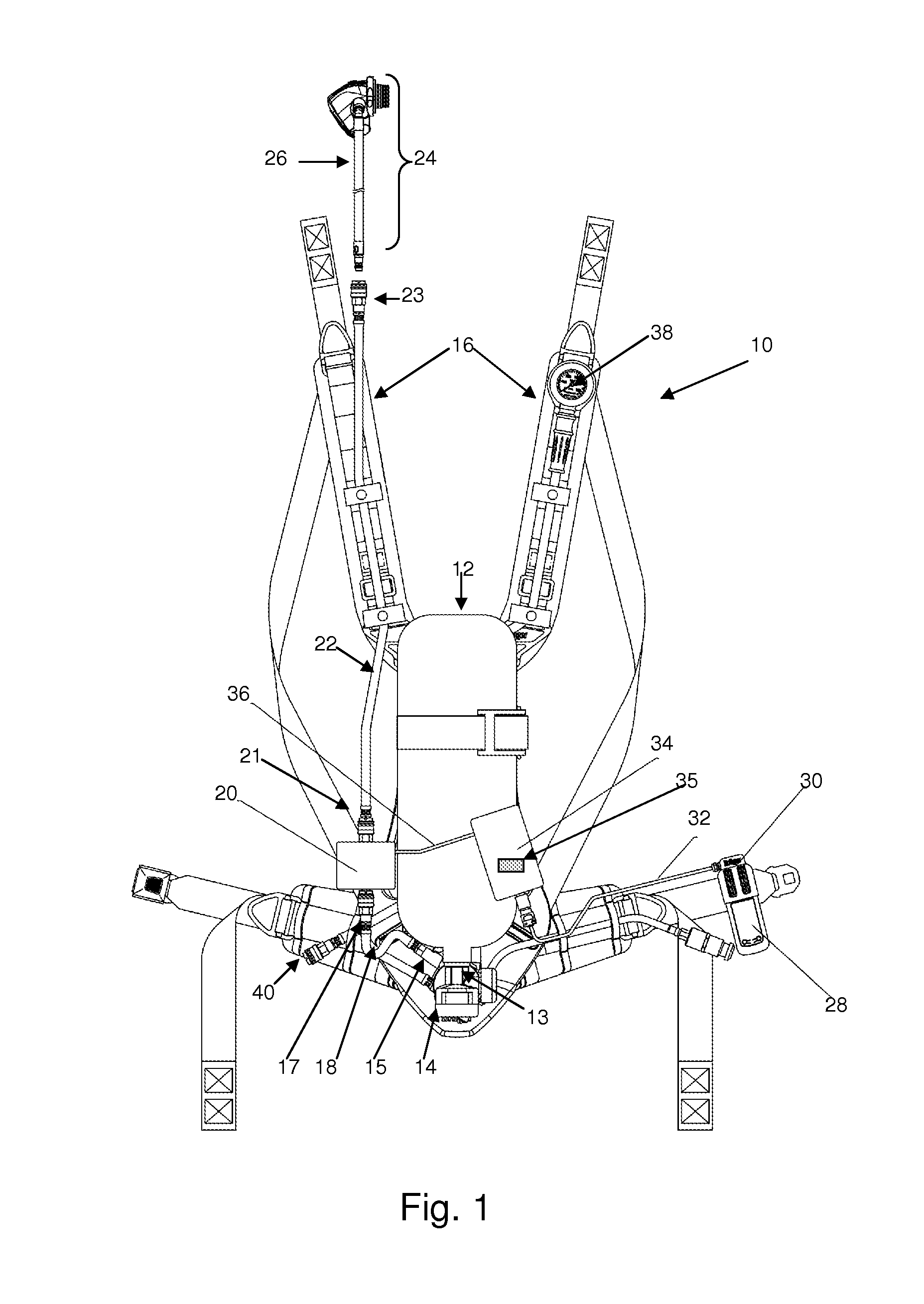
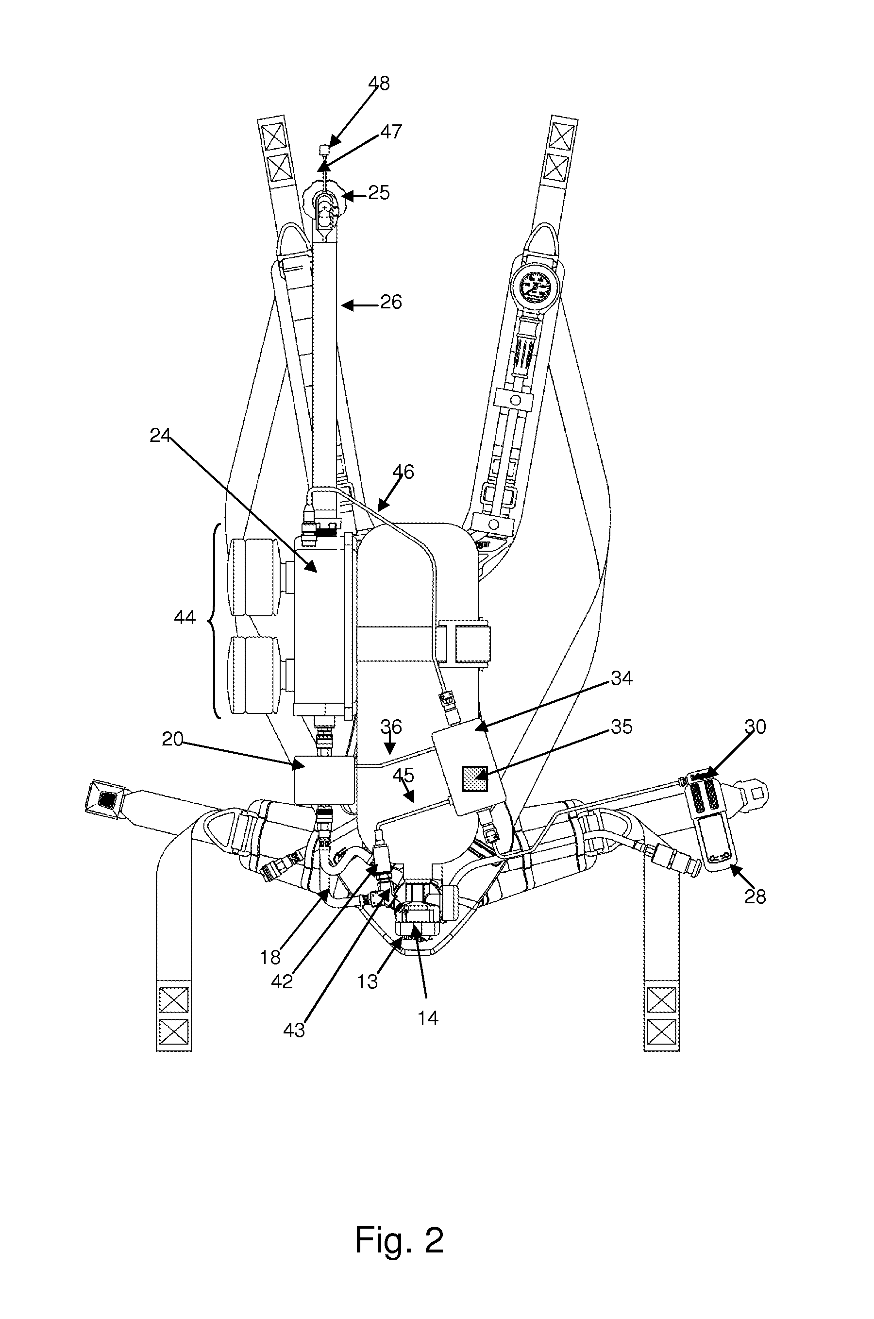
[0036]The breathing apparatus according to invention principles advantageously enables a user to operate a breathing mask in a negative pressure mode allowing intake of filtered ambient air and automatically and immediately switching the mask to operate in a positive pressure mode in response to detecting at least one environmental characteristic indicating that a dedicated source of compressed air is needed. The breathing apparatus advantageously includes at least one sensor for sensing at least one environmental characteristic of the ambient environment. The at least one sensor may sense a plurality of different environmental characteristics that may require a change in the type of breathing mode employed by the apparatus at a given time.

[0037]In a first mode of operation, the mask associated with the breathing apparatus is in negative pressure mode such that the user may intake filtered ambient air. In this first negative pressure mode, an exhalation valve in the mask is selectiv...


PUM


Abstract

A breathing apparatus includes a source of compressed air and a lung demand valve that receives compressed air from the source. A pneumatic valve assembly is connected between the source and the lung demand valve. The pneumatic valve assembly is moveable between a first closed position that prevents a flow of compressed air to the lung demand valve and a second open position that provides a path for compressed air to flow to the lung demand valve. A mask receives the lung demand valve therein. The mask provides the compressed air to a user and having a first operational mode providing filtered ambient air to the user and a second operational mode providing compressed air to the user. A control device is coupled to the pneumatic valve assembly. The control device detects a condition in the air surrounding the apparatus and controlling the pneumatic valve assembly to move between the first closed and second open position and the mask to operate in a respective one of the first and second operational modes.

Description

FIELD OF THE INVENTION[0001]This invention concerns a system and method of using a breathing apparatus, and more specifically, to automatically modify a breathing mode of a breathing apparatus in response to environmental conditions.BACKGROUND OF THE INVENTION[0002]There are many environments where air quality is insufficient for respiration due to insufficient oxygen concentration and / or contamination by unsafe particulate or gaseous matter. Yet, in these environments, it is important to be able to function normally in order to perform certain tasks. An example of this type of environment is a smoke-filled building which must be navigated by firefighters in order to render buildings safe as well as to rescue persons who may be trapped in this environment. Another example of a contaminate-rich environment may include a structure that has been overcome by a gas which may be harmful. This may occur, for example, during a military operation where adversaries release a toxic or otherwis...

Claims


Application Information

Patent Timeline
Patent Type & Authority Applications(United States)
IPC IPC(8): A61M16/00A61M16/08A61M16/20A61M16/06
CPCA61M16/0003A61M16/0087A61M16/0616A61M2205/3331A61M16/205A61M2016/0027A61M16/0875A62B7/02A62B7/10A62B9/02A62B9/04A62B18/08
Inventor ROBEY, ERIC J.
Owner DRAEGER MEDICAL SYST INC
Learn More