Method for Controlling a Multi-Hop Transmission

Inactive Publication Date: 2015-02-19
NOKIA SOLUTIONS & NETWORKS OY
View PDF3 Cites 10 Cited by
  • Summary
  • Abstract
  • Description
  • Claims
  • Application Information

AI Technical Summary

Benefits of technology

[0013]Hence, the basic idea of the present invention is to provide a method b

Problems solved by technology

As mentioned, such a multi-hop connection (two hops or more) might be burdened with additional transmission delay comp

Method used


Image

  • Method for Controlling a Multi-Hop Transmission
  • Method for Controlling a Multi-Hop Transmission
  • Method for Controlling a Multi-Hop Transmission

Examples


first embodiment

[0071]In the following, two specific embodiments will be described. In a first embodiment, each packet designed for a multi-hop transmission may be marked with a timestamp showing generation time of the packet. The timestamp could be added for example in the GTP-U header of the packet but of course it could be added to other headers. The timestamp can be used to estimate the delay already experienced on previous relaying hops. Each node, upon reception of a packet, can check the timestamp in the packet header, compare it with the current time and estimate the already experienced delay.

[0072]An alternative solution could be to include the delay already cumulated for example in the MAC header (but of course other headers can be used). I.e. after the scheduling decision is taken, it will summed the cumulated delay in the current node to the delay already cumulated in the previous nodes and included for example in the MAC header.

[0073]Additionally, it should be known at each stage of th...

second embodiment

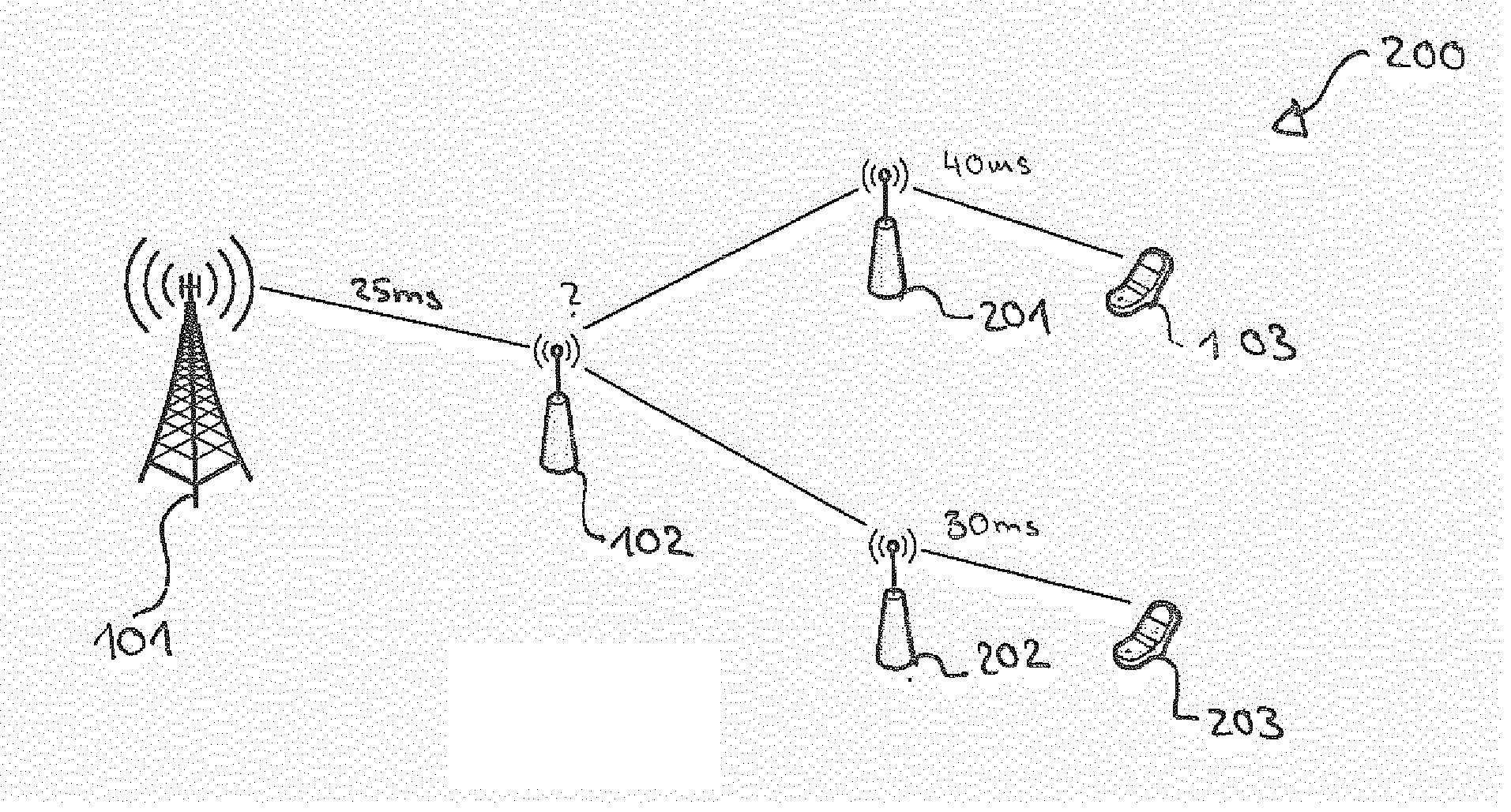
[0081]In the second embodiment, all nodes (DeNB, nested-RNs and end-RNs) collect packet delay measurements from all subordinate and superior nodes and sum them to estimate delay for each subordinating connection (future delay) and for the preceding connection (previous delay).

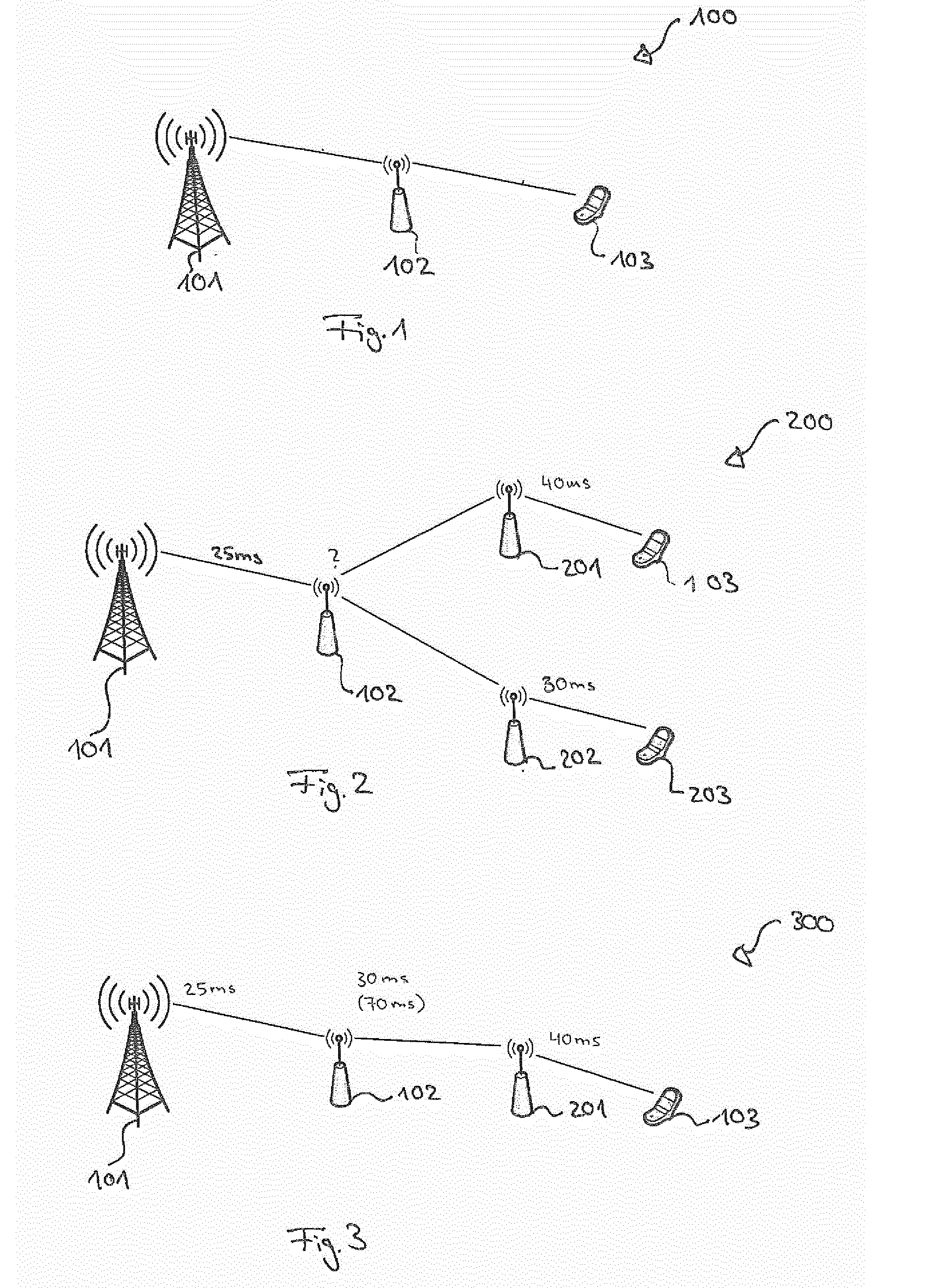
[0082]FIG. 2 shows an example of such a network configuration. The delay between the DeNB 101 and the nested RN 102 may be for example 25 ms. The nested RN estimates this delay as previous delay. It further estimates the delay to RN 201 for example as 40 ms and the delay to RN 202 as 30 ms. Thus, a maximum delay for packets to user equipment 103 may be PDB-20-25-40 [ms] and to user equipment 203 PDB-20-25-30 [ms].

[0083]Depending on the nested-RN functionalities, it could be also possible that the nested-RN can calculate the sum of its own delay measurement and the delay of subordinate RNs, and forward it as the total delay in the part of the network topology supported by the nested-RN. For example as shown in F...


PUM


Abstract

Method for controlling a multi-hop transmission it is described a method for controlling a multi-hop transmission of a data packet between a base station and a user equipment via at least one relay node. A maximum allowable time period for transmitting the data packet between the base station and the user equipment via the at least one relay node is specified. The method includes calculating, based on a time information associated with a time period, which has been needed for a transmission of the data packet to the at least one relay node, and the maximum allowable time period, a remaining time period being available for the at least one relay node for transmitting the data packet, and controlling the transmission of the data packet from the at least one relay node to the base station or the user equipment based on the calculated remaining time period.

Description

FIELD OF THE INVENTION[0001]The present invention relates to the field of communication networks and in particular to communication networks which provide a multi-hop transmission via one or more relay nodes.BACKGROUND OF THE INVENTION[0002]In mobile wireless communication systems, such as the 3GPP Long Term Evolution (LTE, LTE-Advanced), systems may incorporate relaying techniques. Relaying based on dedicated nodes (relay node, RN) might be one of the key solutions in fourth generation (4G) systems (e.g. LTE-A, WMAX).[0003]The LTE Rel. 10 standards define the so called two-hop architecture, i.e. with all relay nodes (RNs) connected directly to a donor eNodeB or base station (DeNB). More advanced concepts consider also multi-hop architectures, with RNs allowed to connect also to other RNs (nested-RN).[0004]A multi-hop connection (two hops or more) might be burdened with additional transmission delay, compared to a direct connection. Each RN in a multi-hop connection adds delay (or t...

Claims


Application Information

Patent Timeline
IPC IPC(8): H04W40/22H04L12/733H04W28/02H04L12/727H04L45/121H04L45/122
CPCH04W40/22H04W28/0236H04L45/20H04L45/121H04W84/047H04L47/28H04W28/021H04L43/0858
Inventor GORA, JACEKREDANA, SIMONEFAERBER, MICHAEL
Owner NOKIA SOLUTIONS & NETWORKS OY
Why Eureka
Try Eureka