Retainer ring structure for chemical-mechanical polishing machine and method for manufacturing the same

a technology of chemical-mechanical polishing machine and retainer ring, which is applied in the manufacture of grinding machine components, metal working apparatus, manufacturing tools, etc., can solve the problems of multi-layer interconnection technology, low strength of retainer ring, and long time-consuming planarization, so as to reduce manufacturing costs, prevent contamination and corrosion of metallic ring, and improve durability

Inactive Publication Date: 2015-02-19
CNUS
View PDF10 Cites 0 Cited by
  • Summary
  • Abstract
  • Description
  • Claims
  • Application Information

AI Technical Summary

Benefits of technology

[0009]An embodiment of the present invention is directed to a retainer ring structure for a CMP machine and a method for manufacturing the same, which prevents external exposure of a metallic ring of a retainer ring structure, thereby preventing contamination and corrosion of the metallic ring and improving durability, and uses a low-priced metallic material to reduce the manufacturing cost, thereby increasing marketability.

Problems solved by technology

The multilayer interconnection technology is an important issue for a sub-micron process.
Since the retainer ring is made of resin such as plastic, the retainer ring has a low strength.
Furthermore, a lot of time is required for a planarization process of the ring before the CMP process, and partial abrasion may occur due to the imbalance of force when a cover bolt is tightened.
In this case, however, there are difficulties in coupling the metallic ring and the resin ring, and thus workability inevitably decreases.
During the coupling operation, boding or welding may be used, but partial abrasion may occur due to the incomplete function and non-uniform coupling.
Furthermore, as bolt holes formed in the metallic ring are exposed to the outside, contamination may occur due to a polishing agent, and corrosion may easily occur to reduce the durability.

Method used


Image

  • Retainer ring structure for chemical-mechanical polishing machine and method for manufacturing the same
  • Retainer ring structure for chemical-mechanical polishing machine and method for manufacturing the same
  • Retainer ring structure for chemical-mechanical polishing machine and method for manufacturing the same

Examples


Embodiment Construction

[0021]Exemplary embodiments of the present invention will be described below in more detail with reference to the accompanying drawings. The present invention may, however, be embodied in different forms and should not be constructed as limited to the embodiments set forth herein. Rather, these embodiments are provided so that this disclosure will be thorough and complete, and will fully convey the scope of the present invention to those skilled in the art. Throughout the disclosure, like reference numerals refer to like parts throughout the various figures and embodiments of the present invention.

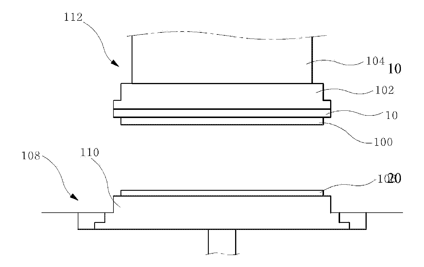
[0022]Referring to FIG. 1, a retainer ring structure 10 according to an embodiment of the present invention will be described as follows.

[0023]A CMP machine includes a main body 108 and a polishing head 112. The main body 108 includes a polishing platen 110 mounted on the top surface thereof and a polishing pad 106 installed on the top surface of the polishing platen 110.

[0024]The polishin...


PUM

PropertyMeasurementUnit
durabilityaaaaaaaaaa
operating speedaaaaaaaaaa
strengthaaaaaaaaaa

Abstract

A retainer ring structure for a chemical-mechanical polishing (CMP) machine includes: an insert ring made of metal and having a plurality of holes formed at the top surface thereof and coupled to a head of the CMP machine; an insert pin made of resin, including a body having a hollow portion of which the top surface is opened and one or more elongated grooves formed at side surfaces thereof in a longitudinal direction, and press-fitted into a hole of the insert ring so as to be subjected to a tapping process; and an outer ring formed to surround the insert pin and the insert ring.

Description

BACKGROUND OF THE INVENTION[0001]The present invention relates to a retainer ring structure for a chemical-mechanical polishing (CMP) machine, and more particularly, to a retainer ring structure for a CMP machine and a method for manufacturing the same, which prevents external exposure of a metallic ring of a retainer ring structure to fix the position of a silicon wafer during a CMP process, thereby preventing contamination and corrosion of the metallic ring and improving durability, and uses a low-priced metallic material to reduce the manufacturing cost, thereby increasing marketability.[0002]With the increase in operating speed and integration degree of semiconductor devices, the increase in number of interconnection layers and the miniaturization of interconnection patterns in a multilayer interconnection structure have been required more and more. The multilayer interconnection technology is an important issue for a sub-micron process.[0003]In particular, as a process margin f...

Claims


Application Information

Patent Timeline
Patent Type & Authority Applications(United States)
IPC IPC(8): B24B37/32
CPCB24B37/32Y10T29/49826
Inventor KIM, BU SOONCHOI, HEUNG SUN
Owner CNUS
Why Eureka
Try Eureka