Ventilation fan and ventilation system

a technology of ventilation system and ventilation fan, which is applied in ventilation system, lighting and heating apparatus, heating types, etc., can solve the problems of management cost, production cost increase, etc., and achieve the effect of reducing production cost or management cos

Active Publication Date: 2015-02-19
PANASONIC INTELLECTUAL PROPERTY MANAGEMENT CO LTD
View PDF11 Cites 23 Cited by
  • Summary
  • Abstract
  • Description
  • Claims
  • Application Information

AI Technical Summary

Benefits of technology

[0009]The ventilation fan and the ventilation system according to the present invention can reduce the production cost or management cost.

Problems solved by technology

For this reason, many kinds of ventilation fans are required depending on the kind of sensor to be installed thereon and installation environments, thus resulting in an increase in production cost, management cost or the like.

Method used


Image

  • Ventilation fan and ventilation system
  • Ventilation fan and ventilation system
  • Ventilation fan and ventilation system

Examples


embodiment 1

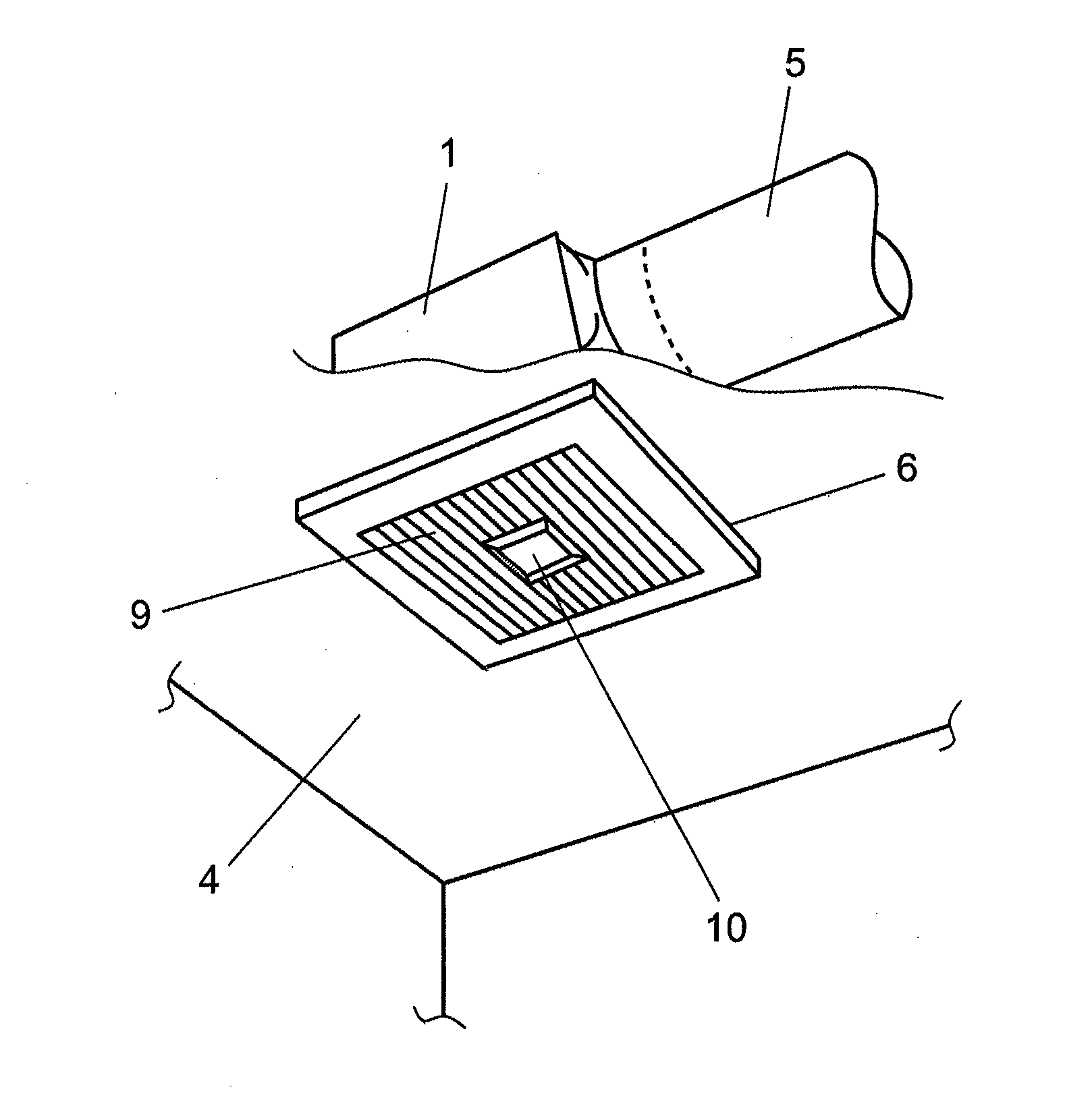
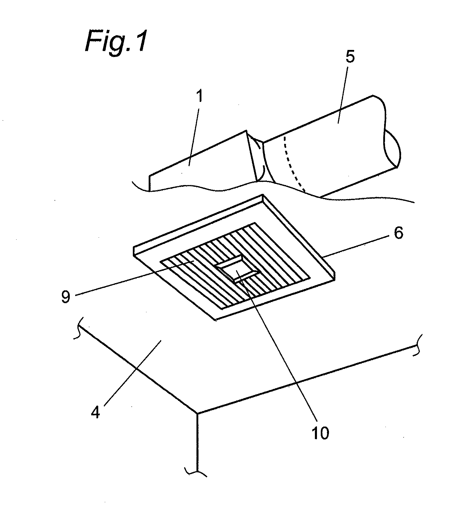
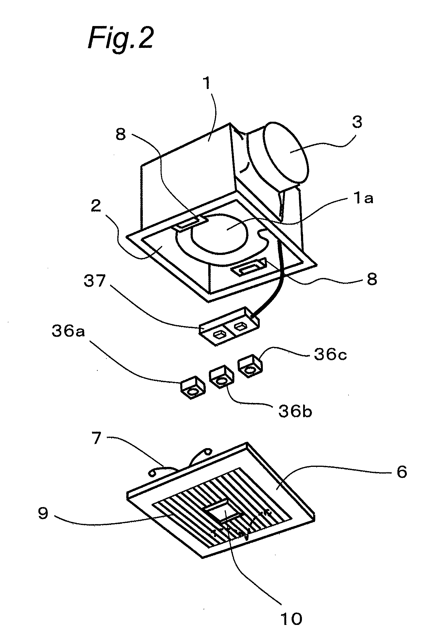
[0051]FIG. 1 is a partially cutaway perspective view of a ventilation fan according to a first embodiment of the present invention, showing an example of installation thereof, and FIG. 2 is an exploded perspective view of the ventilation fan.

[0052]As shown in FIG. 1 and FIG. 2, the ventilation fan 50 includes a body unit 51 having a box-shaped body case 1, and a fan 1a mounted in the body case 1. The body unit 51 is mounted on an upper surface of a ceiling board 4. The body case 1 has an indoor air suction opening 2 defined in a lower surface thereof and an indoor air discharge opening 3 defined in a side surface thereof (this opening may be formed in an upper surface).

[0053]As shown in FIG. 1, the body case 1 is mounted on the upper surface of the ceiling board 4, which has an opening (not shown) of a size nearly equal to that of the indoor air suction opening 2. The indoor air discharge opening 3 in the body case 1 is connected to one end of a duct 5, the other end of which is ext...

embodiment 2

[0086]A ventilation fan according to a second embodiment of the present invention is explained hereinafter with reference to the drawings.

[0087]In FIG. 5 to FIG. 7, a box-shaped body case 61 of the ventilation fan according to the second embodiment has an indoor air suction opening 62 defined in a lower surface thereof and an indoor air discharge opening 63 defined in a side surface (or an upper surface) thereof. A fan 61a is accommodated within the body case 61.

[0088]As shown in FIG. 5, the body case 61 is mounted on an upper surface of a ceiling board 64, which has an opening (not shown) of a size nearly equal to that of the indoor air suction opening 62.

[0089]The indoor air discharge opening 63 in the body case 61 is connected to one end of a duct 65, the other end of which is extended to outdoors.

[0090]As shown in FIG. 5, the body case 61 is mounted on the upper surface of the ceiling board 64 and, in such a state, a decorative board 66 is removably mounted so as to cover the in...

embodiment 3

[0127]A ventilation fan according to a third embodiment of the present invention is explained hereinafter with reference to the drawings.

[0128]In FIG. 15 and FIG. 16, a box-shaped body case 101 of the ventilation fan according to the third embodiment has an indoor air suction opening 102 defined in a lower surface thereof and an indoor air discharge opening 103 defined in a side surface (or an upper surface) thereof. A fan 104 is accommodated within the body case 101.

[0129]As shown in FIG. 15, the body case 101 of the ventilation fan is mounted on an upper surface of a ceiling board 105, which has an opening (not shown) of a size nearly equal to that of the indoor air suction opening 102. The indoor air discharge opening 103 in the body case 101 of the ventilation fan is connected to one end of a duct 106, the other end of which is extended outdoors.

[0130]Also, as shown in FIG. 15, the body case 101 is mounted on the upper surface of the ceiling board 105. In such a state, a decorat...


PUM


Abstract

A ventilation fan includes a body unit, which has a fan disposed in a body case and a fan controller operable to control an air volume of the fan. The ventilation fan also includes a sensor module having an indoor environment detecting sensor and a module controller operable to control a detecting operation of the indoor environment detecting sensor. The body unit has a module mount on which the sensor module is mounted and another sensor module can be mounted in place of the sensor module. The module mount is connected to the fan controller. The module controller outputs detection information obtained based on a detection result of the indoor environment detecting sensor to the fan controller, which in turn controls the air volume of the fan based on the detection information inputted thereto.

Description

TECHNICAL FIELD[0001]The present invention relates to a ventilation fan installed on a ceiling.BACKGROUND ART[0002]A conventional ventilation fan of this kind includes a body case having an indoor air suction opening defined in a lower wall thereof and an indoor air discharge opening defined in a side wall or upper wall thereof, a fan mounted in the body case, and a controller for controlling the operation of the fan. Further, for example, a human body detecting sensor is mounted as a sensor for detecting an indoor environment and connected to the controller. If the presence of a human body is detected by the human body detecting sensor, the controller controls the fan to drive it or increase the air volume (see, for example, Patent Document 1 or 2).Patent Documents[0003]Patent Document 1: JP 6-300341 A[0004]Patent Document 2: JP 2010-117111 ASUMMARY OF THE INVENTION[0005]However, as such a sensor for detecting the indoor environment, there are various sensors such as, for example, ...

Claims


Application Information

Patent Timeline
Patent Type & Authority Applications(United States)
IPC IPC(8): F24F7/007F24F11/00F24F11/76
CPCF24F7/007F24F11/0001F24F11/0034F24F11/0012F24F11/0015F24F11/001F24F11/30F24F2110/10F24F2110/20F24F2110/70F24F2110/72F24F2120/10F24F2130/30F24F11/77Y02B30/70F24F11/56
Inventor SAKAI, HIROSATOSYOUGEN, HIDENORIMORIMOTO, NOBUYUKINAKAJIMA, TSURAKITAKENAWA, SHINGOYAMAGUCHI, MASAHIRODOUMOTO, KAZUKI
Owner PANASONIC INTELLECTUAL PROPERTY MANAGEMENT CO LTD
Why Eureka
Try Eureka