Check patentability & draft patents in minutes with Patsnap Eureka AI!

Audio decoding device, audio coding device, audio decoding method, audio coding method, audio decoding program, and audio coding program

a technology of audio coding and speech encoding, applied in the field of speech encoding devices, speech encoding devices, speech encoding methods, speech encoding programs, etc., can solve the problems of high frequency components, distortions, and differences,

Active Publication Date: 2015-02-19
NTT DOCOMO INC
View PDF16 Cites 25 Cited by
  • Summary
  • Abstract
  • Description
  • Claims
  • Application Information

AI Technical Summary

Benefits of technology

The method described in Patent Literature 1 allows for precise control of the high frequency component of a signal, but it requires dividing the signal into extremely short time segments and calculating and encoding the energy information for each frequency band at each segment. This results in a significant increase in the amount of information, making low bit rate encoding difficult.

Problems solved by technology

In speech encoding, the temporal envelope shape of a decoded signal obtained by decoding a code sequence obtained by encoding an input signal may greatly differ from the temporal envelope shape of the input signal, and such a difference may be perceived as distortions.
Also, when the bandwidth extension techniques are used, since a high frequency component is generated by using a signal obtained by encoding and decoding a low frequency component of a speech signal with the speech encoding techniques as described above, the temporal envelope shape of the high frequency component may likewise differ and such a difference may be perceived as distortions.

Method used


Image

  • Audio decoding device, audio coding device, audio decoding method, audio coding method, audio decoding program, and audio coding program
  • Audio decoding device, audio coding device, audio decoding method, audio coding method, audio decoding program, and audio coding program
  • Audio decoding device, audio coding device, audio decoding method, audio coding method, audio decoding program, and audio coding program

Examples


first embodiment

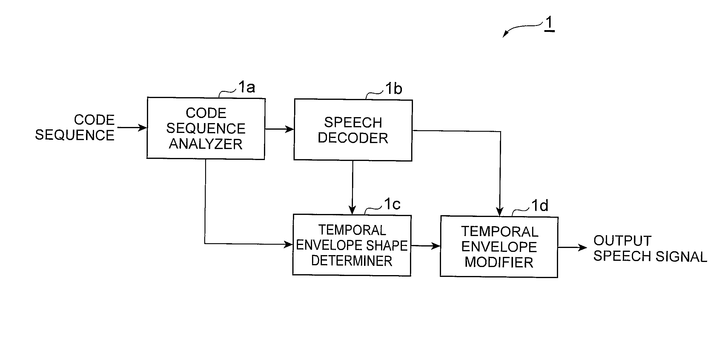
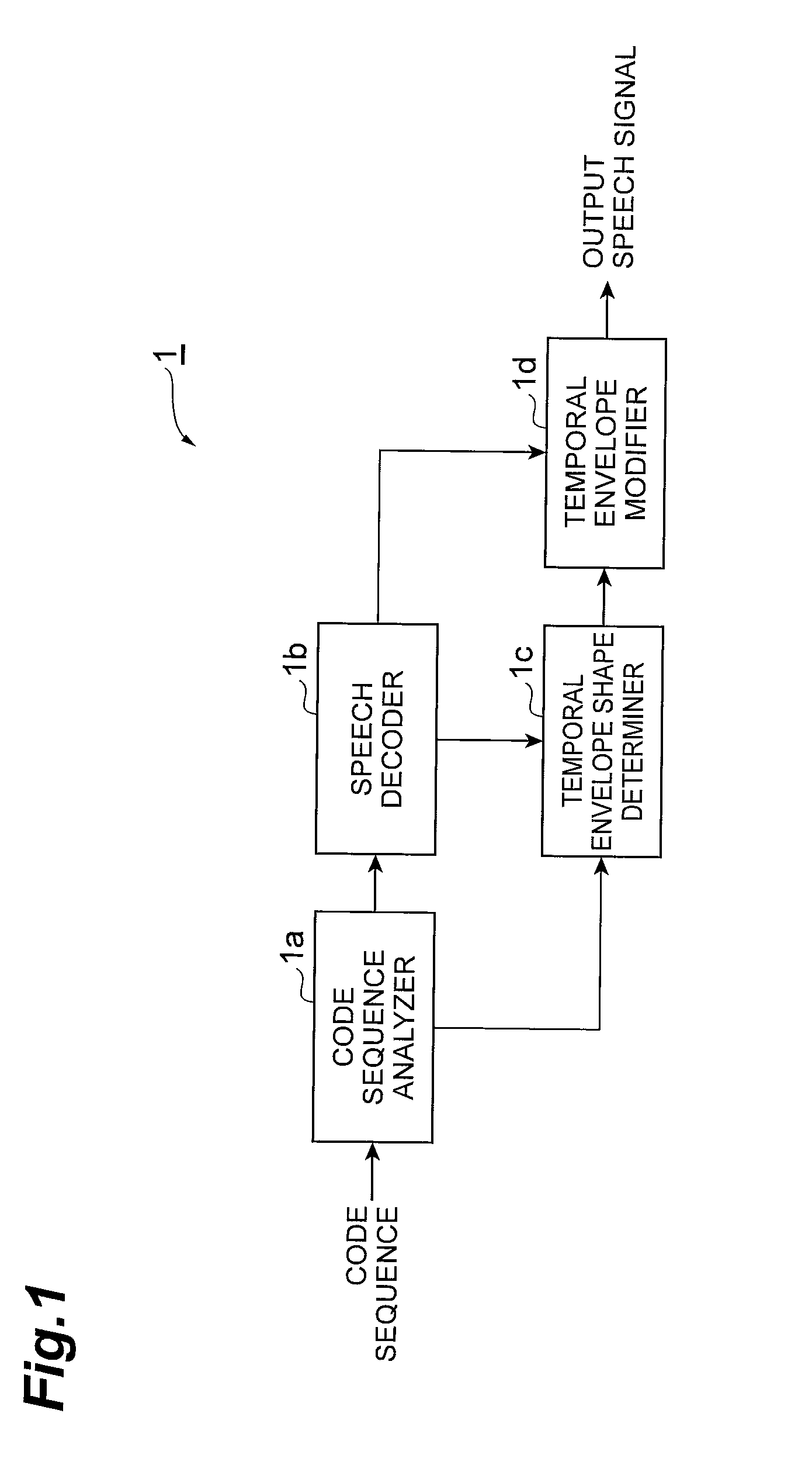
[0373]FIG. 1 is a diagram showing the configuration of a speech decoding device 1 according to a first embodiment. A communication device of the speech decoding device 1 receives a multiplexed code sequence output from a speech encoding device 2 described below and outputs a decoded speech signal to the outside. As shown in FIG. 1, the speech decoding device 1 functionally includes a code sequence analyzer 1a, a speech decoder 1b, a temporal envelope shape determiner 1c, and a temporal envelope modifier 1d.

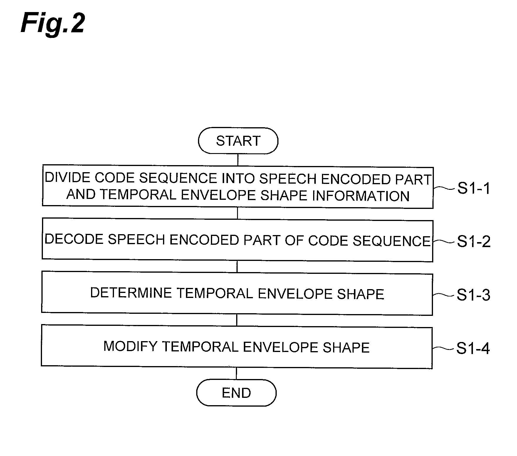
[0374]FIG. 2 is a flowchart showing the operation of the speech decoding device 1 according to the first embodiment.

[0375]The code sequence analyzer 1a analyzes a code sequence and divides the code sequence into a speech encoded part and information about the temporal envelope shape (step S1-1).

[0376]The speech decoder 1b decodes the speech encoded part of the code sequence to obtain a decoded signal (step S1-2).

[0377]The temporal envelope shape determiner 1c determines the tempo...

second embodiment

[0437]FIG. 5 is a diagram showing the configuration of a speech decoding device 100 according to an second embodiment. A communication device of the speech decoding device 100 receives a multiplexed code sequence output from a speech encoding device 200 described below and outputs a decoded speech signal to the outside. As shown in FIG. 5, the speech decoding device 100 functionally includes a code sequence demultiplexer 100a, a low frequency decoder 100b, a low frequency temporal envelope shape determiner 100c, a low frequency temporal envelope modifier 100d, a high frequency decoder 100e, and a low frequency / high frequency signal combiner 100f.

[0438]FIG. 6 is a flowchart showing the operation of the speech decoding device according to the second embodiment.

[0439]The code sequence demultiplexer 100a divides a code sequence into a low frequency encoded part, which is the encoded low frequency signal, and a high frequency encoded part, which is the encoded high frequency signal (ste...

third embodiment

[0463]FIG. 12 is a diagram showing the configuration of a speech decoding device 110 according to a third embodiment. A communication device of the speech decoding device 110 receives a multiplexed code sequence output from a speech encoding device 210 described below and outputs a decoded speech signal to the outside. As shown in FIG. 12, the speech decoding device 110 functionally includes a code sequence demultiplexer 110a, a low frequency decoder 100b, a high frequency decoder 100e, a high frequency temporal envelope shape determiner 110b, a high frequency temporal envelope modifier 110c, and a low frequency / high frequency signal combiner 100f.

[0464]FIG. 13 is a flowchart showing the operation of the speech decoding device according to the third embodiment.

[0465]The code sequence demultiplexer 110a divides a code sequence into a low frequency encoded part, a high frequency encoded part and information about the high frequency temporal envelope shape (step S110-1).

[0466]The high...


PUM


Abstract

An objective of the present invention is to correct a temporal envelope shape of a decoded signal with a small information volume and to reduce perceptible distortions. An audio decoding device which decodes a coded audio signal and outputs an audio signal comprises: a coded series analysis unit that analyzes a coded series which contains the coded audio signal; an audio decoding unit that receives from the coded series analysis unit the coded series which contains the coded audio signal and decodes same, obtaining an audio signal; a temporal envelope shape establishment unit that receives information from the coded series analysis unit and / or the audio decoding unit, and, on the basis of the information, establishes a temporal envelope shape of the decoded audio signal; and a temporal envelope correction unit that, on the basis of the temporal envelope shape which is established with the temporal envelope shape establishment unit, corrects the temporal envelope shape of the decoded audio signal and outputs same.

Description

RELATED APPLICATIONS[0001]This application is a continuation application of PCT / JP2013 / 061105 having an international filing date of Apr. 12, 2013, which claims priority to JP2012-103519 filed Apr. 27, 2012 and JP2012-254496 filed Nov. 20, 2012. This application incorporates PCT / JP2013 / 061105, JP2012-103519 and JP2012-254496 herein by reference.BACKGROUND OF THE INVENTION[0002]1. Field of the Invention[0003]The present invention relates to a speech decoding device, a speech encoding device, a speech decoding method, a speech encoding method, a speech decoding program, and a speech encoding program.[0004]2. Description of the Related Art[0005]Speech encoding for compressing the amount of data of speech signals and audio signals to a few tenths of the original size is an extremely important technique in terms of transmission and accumulation of signals. Examples of speech encoding techniques widely used include code excited linear prediction (CELP) that encodes a signal in a time doma...

Claims


Application Information

Patent Timeline
IPC IPC(8): G10L19/26
CPCG10L19/265G10L19/24G10L21/038
Inventor KIKUIRI, KEIYAMAGUCHI, ATSUSHI
Owner NTT DOCOMO INC
Features
  • R&D
  • Intellectual Property
  • Life Sciences
  • Materials
  • Tech Scout
  • Unparalleled Data Quality
  • Higher Quality Content
  • 60% Fewer Hallucinations
Learn More