Anti-reflection Coating and Optical Member Comprising Same

Active Publication Date: 2015-02-26
RICOH IMAGING COMPANY
View PDF3 Cites 12 Cited by
  • Summary
  • Abstract
  • Description
  • Claims
  • Application Information

AI Technical Summary

Benefits of technology

[0010]Accordingly, the first object of the present invention is to provide an anti-reflection coating

Problems solved by technology

However, it is difficult to stably produce a porous silica layer having extremely high porosity for such a low refractive index.
However, because this anti-reflection coating fails to exhibit optimum anti-reflection performance when formed on a substrate having a refractive index of 1.60 or more, further improvement is desired.
However, because this anti-reflection coating has insufficient weathering-preventing effects, further improvement is desired.
Further, when these anti-reflection

Method used


Image

  • Anti-reflection Coating and Optical Member Comprising Same
  • Anti-reflection Coating and Optical Member Comprising Same
  • Anti-reflection Coating and Optical Member Comprising Same

Examples


Example

Example 1

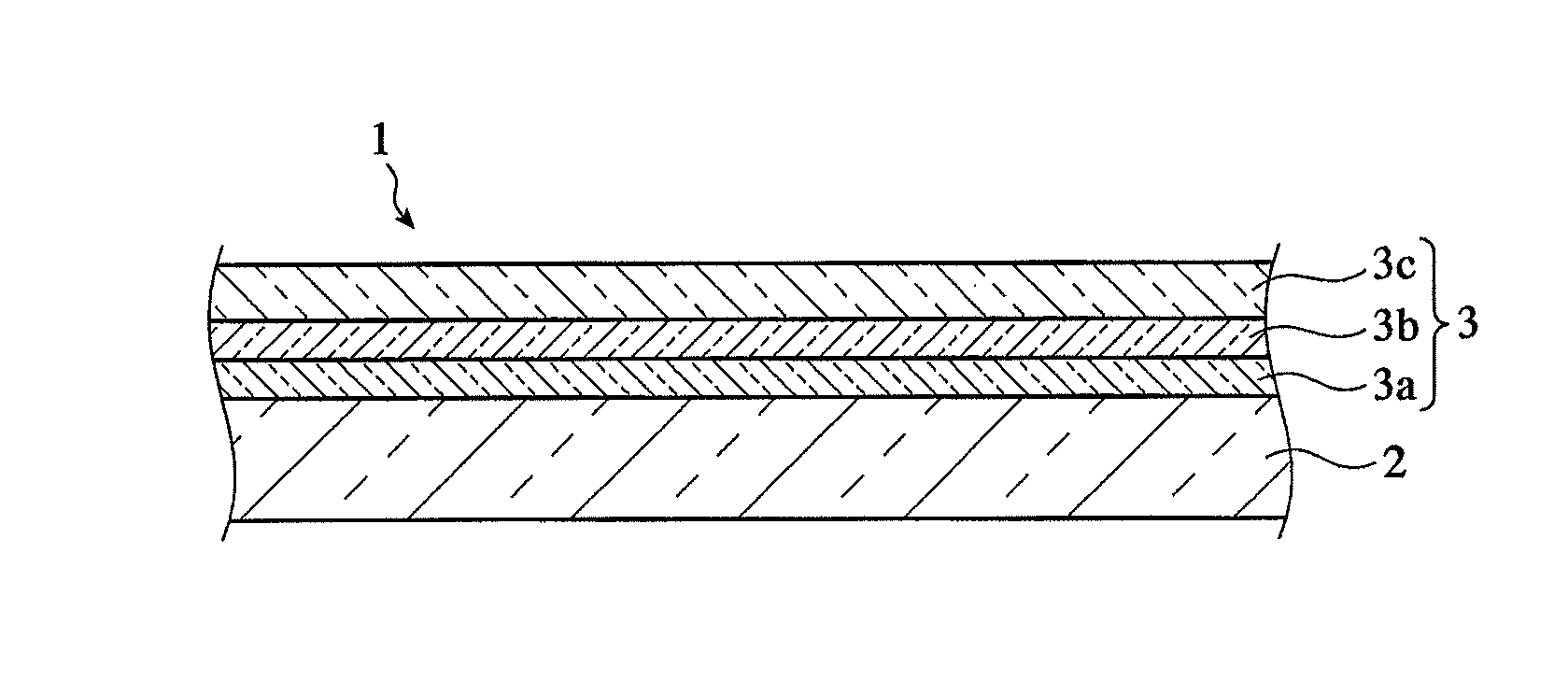
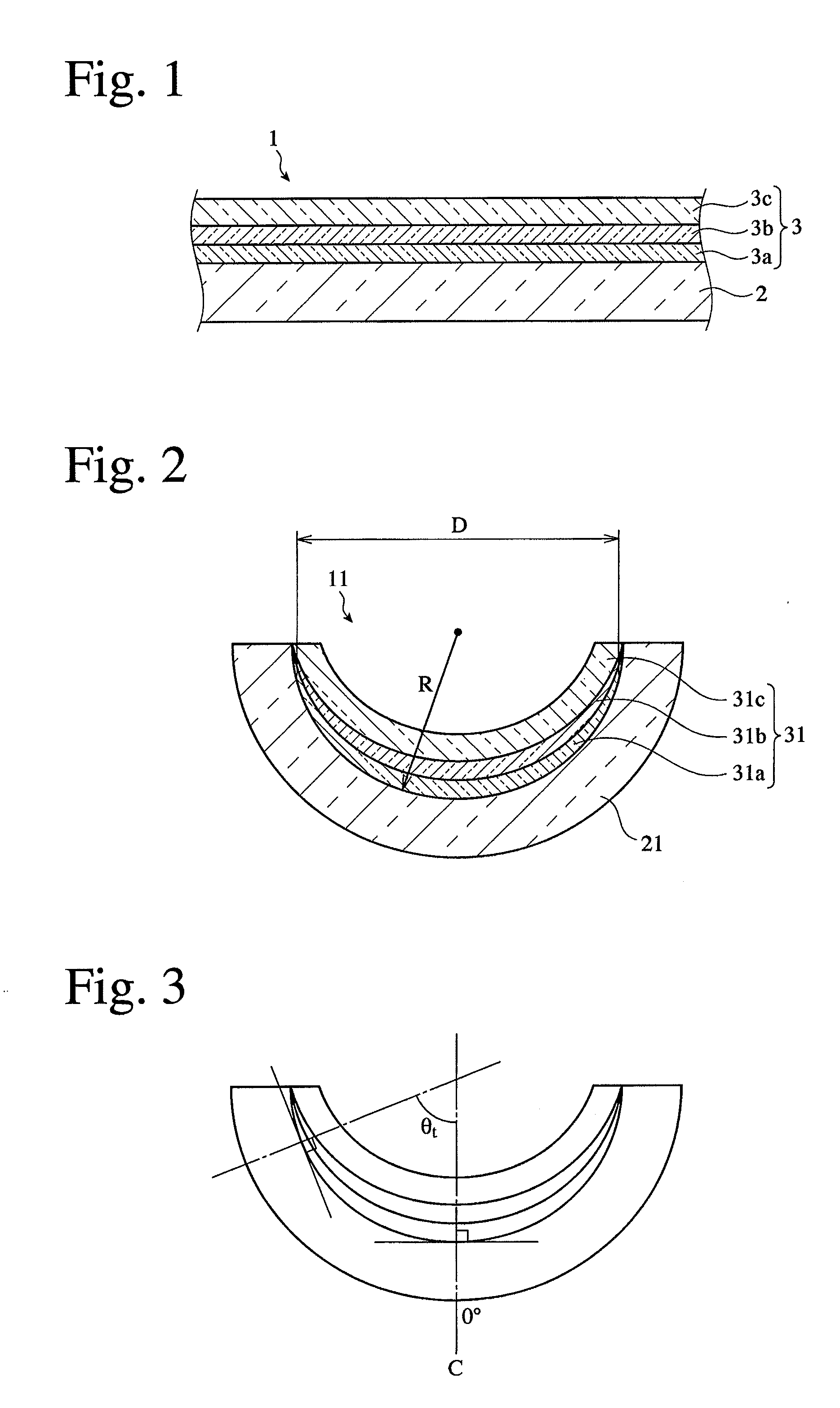
[0151]A first layer of MgF2, a second layer of Ta2O5+Y2O3+Pr6O11, and a third layer of silica aerogel were formed to the optical thickness shown in Table 1 on a flat glass plate of LaSF010 (refractive index: 1.839), to produce each Sample a to g. Because each of the first and second layers formed on a lens substrate having a large maximum inclination angle becomes gradually thinner as it goes from the center toward the periphery (as the inclination angle becomes larger) as shown in FIG. 2, the thickness of the first and second layers in each Sample a to g was set equal to the thickness at a lens substrate inclination angle of 0°, 10°, 20°, 30°, 40°, 50° and 60°, respectively, and the thickness of the third layer was set constant, to evaluate anti-reflection performance at each inclination angle of the lens substrate.

TABLE 1-1LayerMaterialRefractive IndexSubstrateLaSF0101.839FirstMgF21.388LayerSecondTa2O5 + Y2O3 + Pr6O112.055LayerThirdSilica Aerogel1.270Layer

TABLE 1-2Optical...

Example

Comparative Example 1

[0167]Anti-reflection coatings (Samples a to g) were produced in the same manner as in Example 1, except for using Al2O3 and SiO2 as materials for forming the first and second layers, and changing the optical thickness of the first to third layers as shown in Table 2. The anti-reflection coatings of these samples correspond to conventional ones designed to have a refractive index gradually decreasing from the first layer toward the third layer.

TABLE 2-1LayerMaterialRefractive IndexSubstrateLaSF0101.839FirstAl2O31.640LayerSecondSiO21.469LayerThirdSilica Aerogel1.250Layer

TABLE 2-2Optical Thickness [nm]Sam-Sam-Sam-Sam-Sam-Sam-Sam-Layerple aple bple cple dple eple fple gSub-———————strateFirst114113109103958470LayerSecond25252423211815LayerThird126126126126126126126LayerAngle(1)0102030405060Note:(1)A corresponding inclination angle (°) of the lens substrate.

[0168]The spectral reflectance of Sample a (corresponding to a substrate inclination angle of 0°) thus obtained...

Example

Comparative Example 2

[0169]As shown in Table 3, an optical member comprising a seven-layer anti-reflection coating was produced.

[0170](1) Formation of First to Sixth Layers

[0171]Using the apparatus shown in FIG. 21, first to sixth layers were formed in this order on a flat glass plate of LaSF010 (refractive index: 1.839) by a vacuum vapor deposition method with electron beams, as shown in Table 3. The vapor deposition was conducted at an initial degree of vacuum of 1.2×10⁻⁵ Torr and a substrate temperature of 230° C.

[0172](2) Formation of Seventh Layer

[0173]The seventh layer of silica aerogel layer was formed in the same manner as in the third layer of Example 1, except for changing the optical thickness as shown in Table 3.

TABLE 3-1LayerMaterialRefractive IndexSubstrateLaSF0101.839FirstAl2O31.640LayerSecondTa2O5 + Pr6O11 + Y2O32.055LayerThirdMgF21.388LayerFourthTa2O5 + Pr6O11 + Y2O32.055LayerFifthMgF21.388LayerSixthTa2O5 + Pr6O11 + Y2O32.055LayerSeventhSilica Aerogel1.250Layer

TABLE...


PUM

PropertyMeasurementUnit
Angleaaaaaaaaaa
Nanoscale particle sizeaaaaaaaaaa
Thicknessaaaaaaaaaa

Abstract

An anti-reflection coating having an three-layer structure comprising first to third layers formed in this order on a substrate, the substrate having a refractive index of 1.6-1.9, the first layer having a refractive index of 1.37-1.57, the second layer having a refractive index of 1.75-2.5, and the third layer having a refractive index of 1.18-1.32, to light in a wavelength range of 550 nm; the third layer being formed by silica aerogel; and the first and second layers containing no Al2O3.

Description

FIELD OF THE INVENTION[0001]The present invention relates to an anti-reflection coating having a three- or four-layer structure containing no Al2O3, and an optical member comprising the anti-reflection coating.BACKGROUND OF THE INVENTION[0002]A high-performance, single-focus or zoom lens unit for photograph cameras, broadcasting cameras, etc. generally has about 5-40 lenses in a lens barrel. There are also wide-angle lenses for wide image, which have large incident angles of light beams in peripheral portions. Also, a lens having a small radius of curvature to its effective diameter is sometimes disposed in a light path for optical design. Formed on optical members such as these lenses are multi-layer, anti-reflection coatings comprising a combination of dielectric films having different refractive indices for utilizing interference effects with dielectric film thickness of ½λ or ¼λ to a center wavelength λ.[0003]JP 2009-193029 A discloses an anti-reflection coating comprising a fir...

Claims


Application Information

Patent Timeline
IPC IPC(8): G02B1/11
CPCG02B1/115G02B1/11G02B5/286
Inventor TAMADA, TAKAAKISASAKI, NAOHITONAKAYAMA, HIROYUKI
Owner RICOH IMAGING COMPANY
Why Eureka
Try Eureka