
Microseismic event localization using both direct-path and head-wave arrivals

Active Publication Date: 2015-02-26
SEISMIC INNOVATIONS
View PDF0 Cites 5 Cited by
  • Summary
  • Abstract
  • Description
  • Claims
  • Application Information

AI Technical Summary

Benefits of technology

The present invention is about using head waves to improve the accuracy of locating small seismic events, especially in the depth dimension. The method involves analyzing both direct path arrivals and head waves. Additionally, the invention includes techniques known as multipath analysis. Overall, the invention enhances the ability to locate microseismic events with greater precision.

Problems solved by technology

However, these modern techniques are still adversely affected by the presence of multipath arrivals of microseismic energy.
If not correctly identified and analyzed, these indirectly arriving wavefronts can cause false positive detection of additional events believed to originate across the layer interfaces that generate them (see B. Fuller et al., Seismic wave phenomena and implications for accuracy of microseismic results, Recorder, 2010).
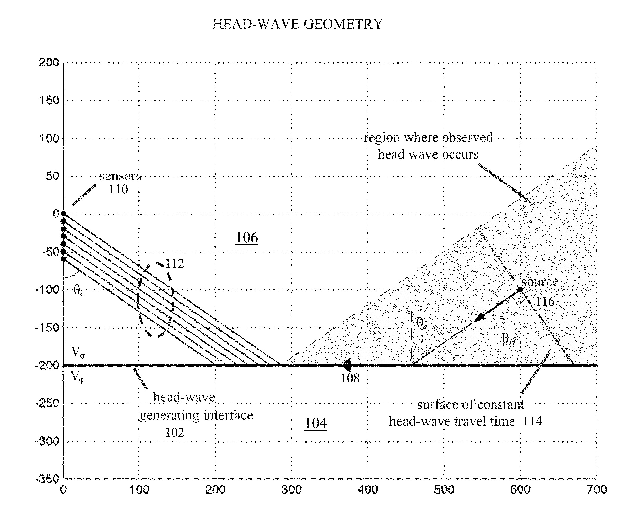
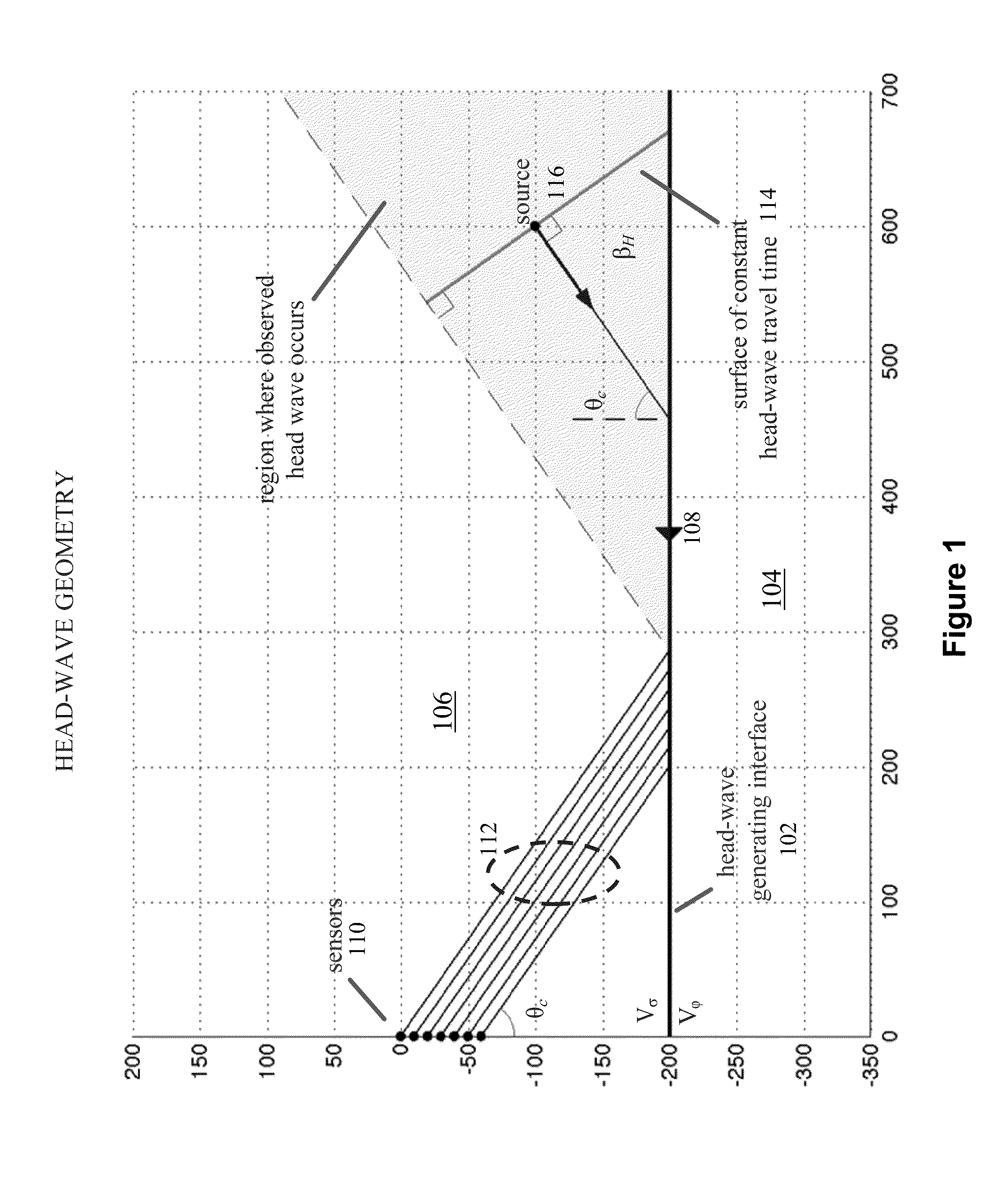
This property of head waves can cause further complications for standard analysis techniques, which typically look to only the first arrival associated with any particular microseismic event.
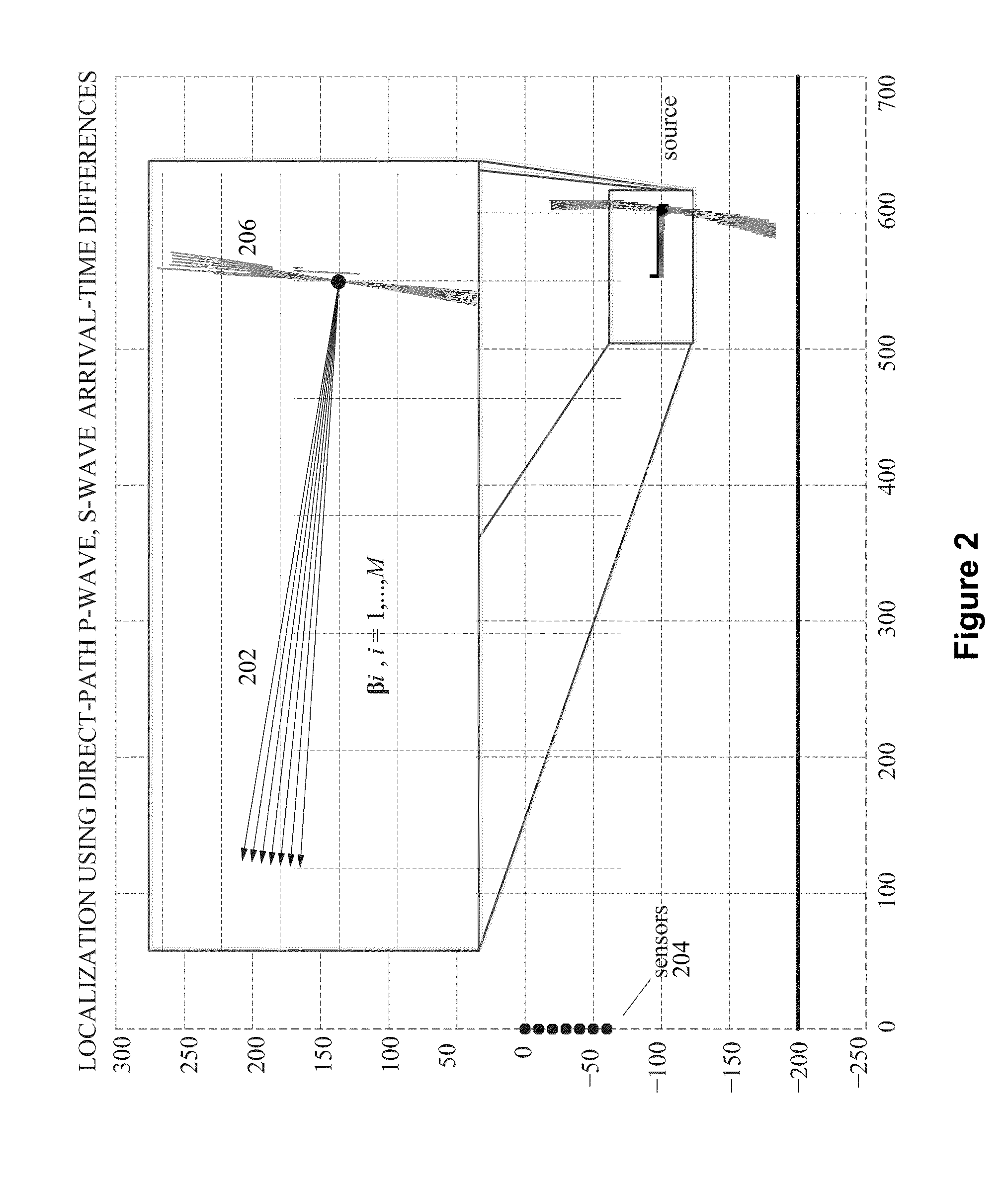
More recent discussions of head waves in microseismic analysis have begun to address combining earlier arriving head waves with later direct-path arrivals during localization for improved accuracy (U. Zimmer, Localization of microseismic events using headwaves and direct waves, SEG Expanded Abstracts, 2010; Microseismic design studies, Geophysics, 2011), but have not addressed the combination of these two arrival types in general and have assessed the benefit of their combination only through travel-time-residual analysis, which obscures the underlying localization geometry and fails to provide an intuitive understanding of the associated effects on accuracy.
These indirect arrivals, which include reflections and head waves, have traditionally been viewed as a nuisance in microseismic analysis, potentially causing additional false-positive event detections and erroneous localizations into the layers which generate them.
This approach affords limited event depth estimation accuracy in surveys where the source-to-receiver-array distances are large, due to typically small relative array apertures, and is adversely affected by the presence of multiple, indirect-path arrivals.
Improper identification and analysis of these head waves can cause gross localization errors of microseismic events across the head-wave-generating interface and into the high-velocity layer.

Method used


Image

  • Microseismic event localization using both direct-path and head-wave arrivals
  • Microseismic event localization using both direct-path and head-wave arrivals
  • Microseismic event localization using both direct-path and head-wave arrivals

Examples


examples

[0058]The above described multipath-analysis microseismic localization technique was applied to a data set collected during hydraulic fracture stimulation of the Montney formation in Alberta. The Montney is bounded below by the higher-velocity Belloy formation. A slightly deviated array of 12 3C geophones was used to monitor the stimulation from near the top of the Montney formation, spanning a vertical height of approximately 100 meters, 200 to 300 meters above the Belloy interface. This configuration resulted in clear head-wave arrivals being observed in collected event data for a wide range of event locations, with the majority of high-energy activity occurring at horizontal displacements of 600 to 1000 meters.

[0059]This survey was first processed using industry standard techniques without accounting for head waves from the deeper fast layer associated with the Belloy formation. As described above in connection with FIG. 9, these microseismic analysis results show events spanning...


PUM


Abstract

The present invention relates to methods and apparatuses for using head waves to greatly improve microseismic event localization accuracy, particularly in the depth dimension, by analyzing them in addition to direct path arrivals whenever they are observed. Embodiments of the invention also include techniques known as multipath analysis.

Description

CROSS-REFERENCE TO RELATED APPLICATIONS[0001]This application is a continuation-in-part of PCT / US2013 / 040191, filed May 8, 2013, which claims the benefit of Provisional Patent Application Ser. No. 61 / 644,337, filed May 8, 2012, each of which is hereby incorporated by reference in its entirety.FIELD OF THE INVENTION[0002]The present invention relates generally to characterizing microseismic events, and more particularly to microseismic event localization using both direct-path and head-wave arrivals.BACKGROUND OF THE RELATED ART[0003]Several techniques have been developed in recent years for the automatic detection and localization of microseismic events associated with hydraulic fracturing treatments in unconventional resource plays, providing large advancements in the reliability of microseismic analysis. However, these modern techniques are still adversely affected by the presence of multipath arrivals of microseismic energy. In many unconventional shale plays, the resource bearin...

Claims


Application Information

Patent Timeline
IPC IPC(8): G01V1/30G01V1/40
CPCG01V1/40G01V1/30G01V2210/123G01V2210/612G01V1/28G01V1/288G01V2210/129
Inventor ABEL, JONATHAN S.
Owner SEISMIC INNOVATIONS
Learn More