Gas Turbine Combustion System

a combustion system and gas turbine technology, applied in the ignition of turbine/propulsion engines, engine starters, lighting and heating apparatus, etc., can solve the problems of increased discharge amount of unburned hydrocarbons, unburned hydrocarbons, and high probability of hydrogen entering the turbine, so as to reduce the unburned content of gas fuel

Inactive Publication Date: 2015-03-05
MITSUBISHI HITACHIPOWER SYST LTD
View PDF51 Cites 41 Cited by
  • Summary
  • Abstract
  • Description
  • Claims
  • Application Information

AI Technical Summary

Benefits of technology

[0009]The present invention can minimize the unburned content of the gas fuel under all load conditions from partial load to rated load. Thus, the discharge amount of, for example, CO and unburned hydrocarbon can be reduced even by using a gas fuel containing therein H2 and CO.

Problems solved by technology

When such a gas fuel is used, an ignition failure can cause the gas fuel to be discharged unburned from a combustor, resulting in hydrogen being likely to enter a turbine.
While the fuel concentration is reduced, flame temperatures decrease to cause incomplete combustion of the gas fuel to occur, resulting in an increased discharge amount of unburned content such as CO and unburned hydrocarbon.

Method used


Image

  • Gas Turbine Combustion System
  • Gas Turbine Combustion System
  • Gas Turbine Combustion System

Examples


first embodiment

1. Gas Turbine Plant

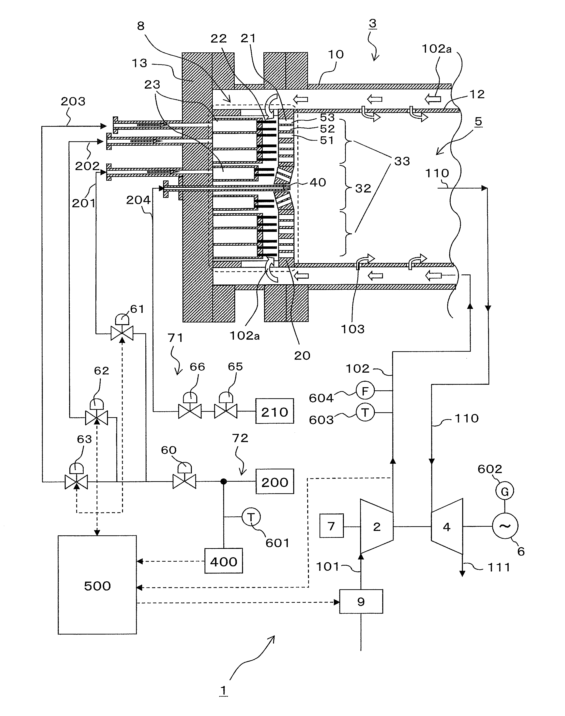
[0021]FIG. 1 is an exemplary configuration diagram showing a gas turbine plant that incorporates a gas turbine combustion system according to a first embodiment of the present invention.

[0022]The gas turbine plant 1 shown in FIG. 1 includes a gas turbine and a generator 6 driven by the gas turbine. The gas turbine includes a compressor 2, a gas turbine combustion system, and a turbine 4. The compressor 2, the turbine 4, and the generator 6 each have a rotor connected coaxially with each other. The gas turbine combustion system, including a combustor 3 as one of its main components, will be described later.

[0023]Operation of the gas turbine plant 1 is as follows. Specifically, air 101 drawn in from the atmosphere is compressed by the air compressor 2 and compressed air 102 is supplied to the combustor 3. The combustor 3 burns a gas fuel together with the compressed air 102 to thereby generate a combustion gas 110. The turbine 4 is driven by the combustion gas 110 ...

second embodiment

[0065]FIG. 7 is an exemplary configuration diagram showing a gas turbine plant that incorporates a gas turbine combustion system according to a second embodiment of the present invention. In FIG. 7, like or corresponding parts are identified by the same reference numerals as those used in the first embodiment of the present invention and descriptions for those parts will not be duplicated.

[0066]The second embodiment of the present invention differs from the first embodiment in that a bleed adjusting valve 11 of an inlet bleed heat (IBH) system that returns the compressed air 102 compressed by the compressor 2 to the inlet of the compressor 2 constitutes the air flow rate adjusting system. The IBH system increases the temperature of the compressed air 102 and reduces the air flow rate by returning part of the compressed air 102 to the inlet of the compressor 2. The IBH system achieves an effect equivalent to that achieved by the IGV. The bleed adjusting valve 11 adjusts the flow rate...

third embodiment

[0068]FIG. 8 is an exemplary configuration diagram showing a gas turbine plant that incorporates a gas turbine combustion system according to a third embodiment of the present invention. In FIG. 8, like or corresponding parts are identified by the same reference numerals as those used in the first embodiment of the present invention and descriptions for those parts will not be duplicated.

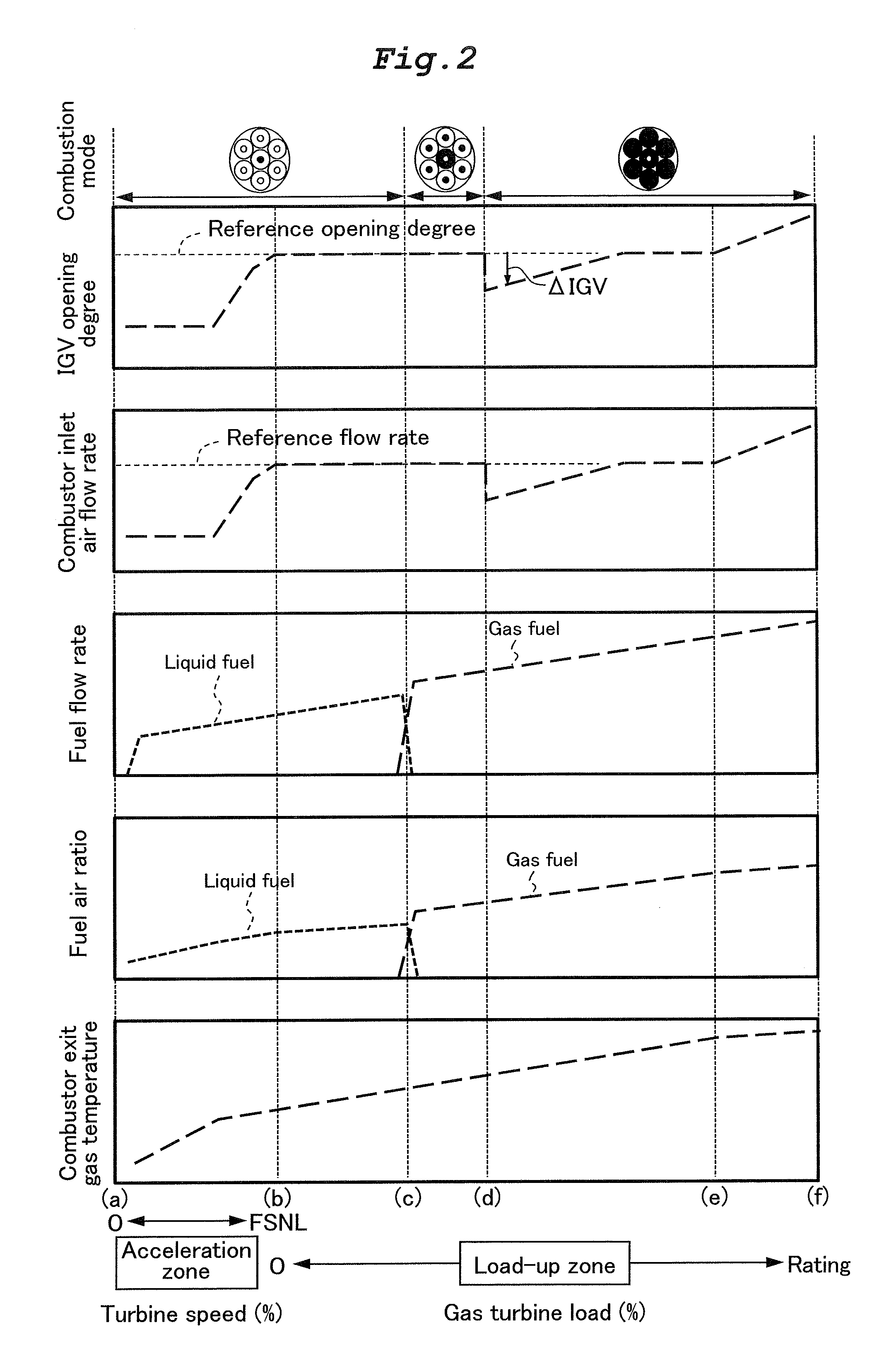
[0069]The third embodiment of the present invention differs from the first and second embodiments in that a bleed adjusting valve 14 constitutes the air flow rate adjusting system, the bleed adjusting valve 14 being disposed in a bypass system that bypasses air bled from the compressor 2 to the turbine 4. The bypass system bleeds part of the compressed air as cooling air for cooling parts that are hot in the turbine 4. The combustor inlet air flow rate can be controlled as shown in FIG. 2 by adjusting the opening degree of the bleed adjusting valve 14. An IGV 9 or an IBH, though not shown in FIG. 8,...


PUM


Abstract

The present invention provides a gas turbine combustion system capable of minimizing unburned content of a gas fuel under all load conditions from partial load to rated load.A gas turbine combustion system includes: a plurality of gas fuel burners 32, 33; an IGV 9 that adjusts a flow rate of air to be mixed with a gas fuel; and a control system 500 that temporarily reduces an air flow rate from a reference flow rate to a set flow rate by outputting a signal to the IGV 9 when a combustion mode is switched from a partial combustion mode in which the gas fuel is burned with part of the gas fuel burners 32, 33 to a full combustion mode in which the gas fuel is burned with all of the gas fuel burners 32, 33.

Description

BACKGROUND OF THE INVENTION[0001]1. Field of the Invention[0002]The present invention relates to a gas turbine combustion system.[0003]2. Description of the Related Art[0004]Researches are currently underway into an effective utilization of by-product gases, such as a coke oven gas produced as a by-product in iron works and an off-gas produced as a by-product in oil refineries, from the standpoints of, for example, reduction in power generation cost, effective utilization of resources, and prevention of global warming. In the integrated coal gasification combined cycle (IGCC) that generates power by gasifying coal as an abundantly available resource, measures are being studied that use a system for capturing and storing a carbon content in a gas fuel supplied to a gas turbine (carbon capture and storage (CCS)) to replace the carbon content in coal with hydrogen (H2), thereby reducing a discharge amount of carbon dioxide (CO2) (see, for example, JP-2013-139975-A).SUMMARY OF THE INVEN...

Claims


Application Information

Patent Timeline
Patent Type & Authority Applications(United States)
IPC IPC(8): F02C3/22F02C9/40F02C9/18F02C7/26F02C7/228
CPCF02C3/22F02C7/26F02C9/40F02C9/18F02C7/228F01D19/00F02C3/24F02C9/50F02C9/52F02C9/54F05D2260/85F05D2270/08F23N1/022F23R3/26F23R3/286F23R3/343F23R3/36F23N2221/10F23N2241/20Y02E20/16
Inventor ASAI, TOMOHIROHAYASHI, AKINORIAKIYAMA, YASUHIRO
Owner MITSUBISHI HITACHIPOWER SYST LTD
Why Eureka
Try Eureka