Supercharge Your Innovation With Domain-Expert AI Agents!

Demodulator for wireless power transmitter

a demodulator and wireless power technology, applied in the direction of amplitude demodulation, near-field systems using receivers, inductance, etc., can solve the problems of ungenerally recognized problems and changes in the reception rate of packets, and achieve the effect of improving the reception rate and improving the reception ra

Active Publication Date: 2015-03-12
ROHM CO LTD
View PDF8 Cites 3 Cited by
  • Summary
  • Abstract
  • Description
  • Claims
  • Application Information

AI Technical Summary

Benefits of technology

This patent describes a system where a receiver can demodulate a received signal using multiple different units. This allows for stable reception regardless of changes in the load current or other factors that may affect the coil voltage or current. The demodulating units can also include a diode rectifier circuit and a bridge circuit to improve reception rates under different load currents. The demodulator can be monolithically integrated on a single semiconductor substrate, which saves circuit area and ensures consistent characteristics. Overall, this system provides more reliable and efficient reception of signals.

Problems solved by technology

Accordingly, in a case in which the demodulator 208 is designed such that it is optimized for a predetermined bias point (load current), when the load changes, the packet reception rate changes, which is a problem.
It should be noted that this problem has not been generally recognized by those skilled in this art.

Method used


Image

  • Demodulator for wireless power transmitter
  • Demodulator for wireless power transmitter
  • Demodulator for wireless power transmitter

Examples


first modification

[First Modification]

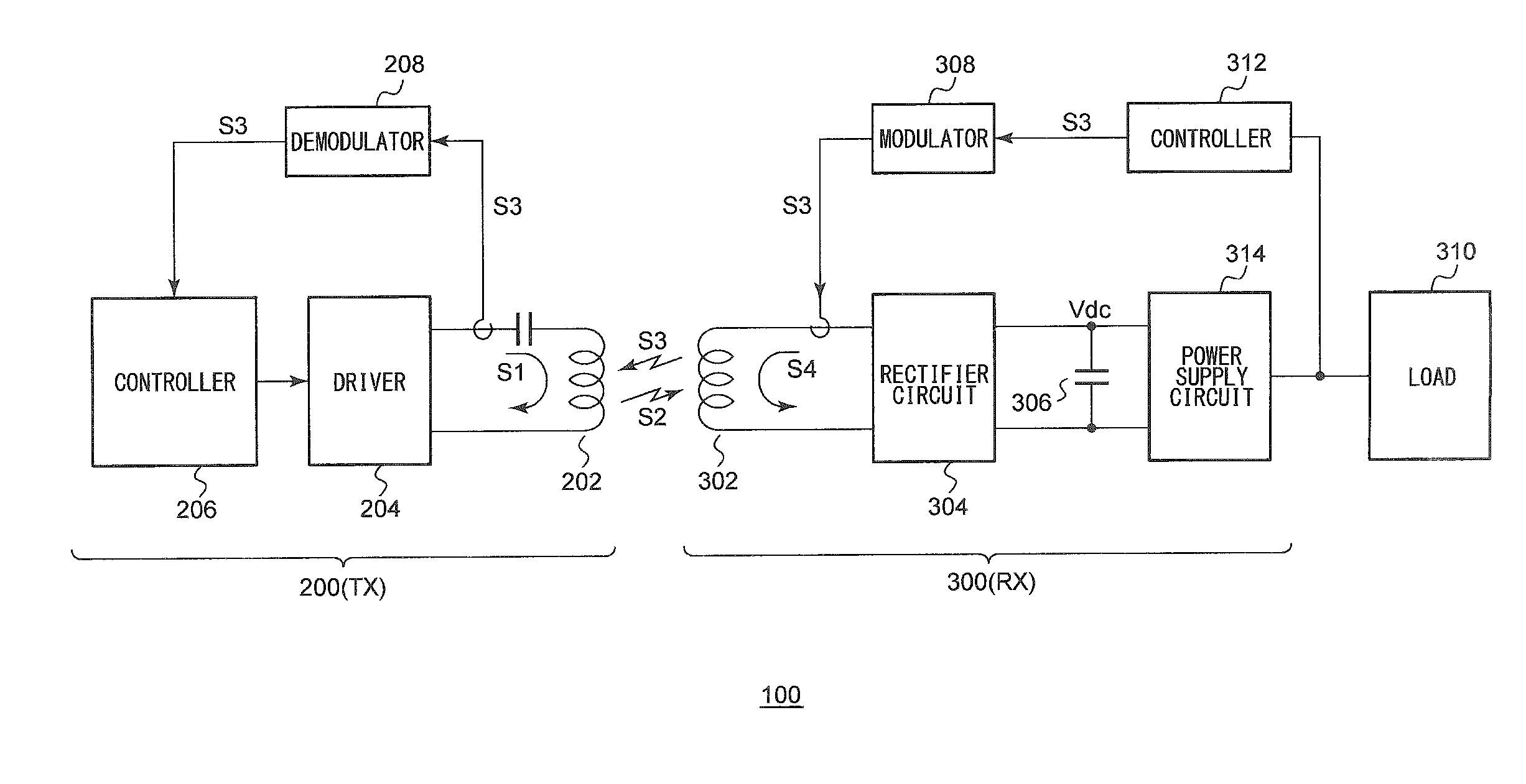
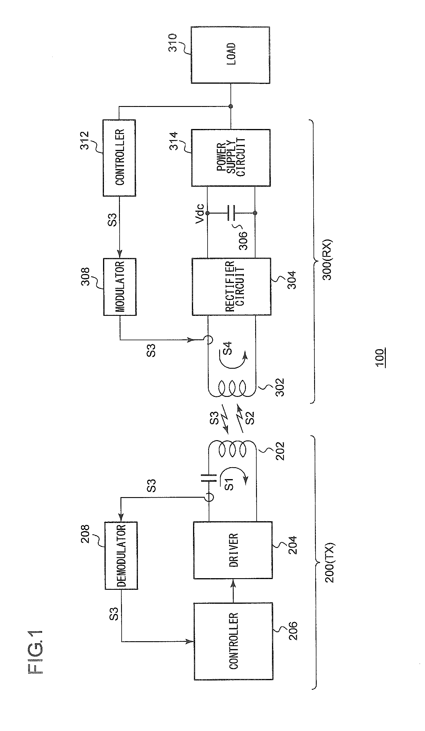
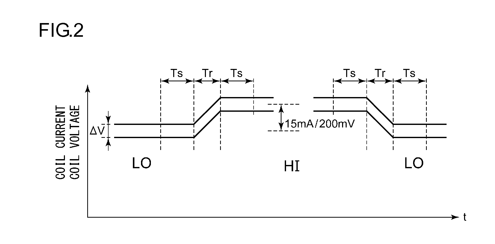
[0065]The combination of the configurations of the multiple demodulators 230 and the combination of the modes employed in the multiple demodulators 230 are not restricted in particular. The backscatter-modulated signal may be demodulated using any one of known techniques.

[0066]Description has been made in the embodiment regarding an arrangement in which the multiple demodulating units 230 each generate a baseband signal S5 as a demodulated signal based on the coil current ICOIL. Also, a part of or all of the demodulators 230 may generate respective baseband signals S5 as demodulated signals based on the coil voltage VCOIL.

second modification

[Second Modification]

[0067]Description has been made in the embodiment regarding a wireless power transmitter that conforms to the Qi standard. The present invention is not restricted to such an arrangement. Also, the present invention is applicable to a wireless power transmitter employed in a system that resembles the Qi standard. Also, the present invention is applicable to a power transmitter 200 that conforms to a standard which will be developed in the future.


PUM


Abstract

A demodulator is mounted on a wireless power transmitter that conforms to the Qi standard, and demodulates an amplitude modulated signal superimposed on a coil current ICOIL that flows through a primary coil of a transmission antenna, or otherwise on a coil voltage across both ends of the primary coil. Multiple demodulating units are each configured to have respectively different configurations, to operate in parallel, to extract a demodulated component from the coil current ICOIL or otherwise from the coil voltage, and to generate baseband signals as demodulated signals. A signal processing unit employs a baseband signal that is correctly received, from among the multiple baseband signals generated by the multiple demodulating units, based on an error detection result obtained using a checksum.

Description

CROSS REFERENCE TO RELATED APPLICATION[0001]The present invention claims priority under 35 U.S.C. §119 to Japanese Application No. 2013-133089 filed Jun. 25, 2013, the entire content of which is incorporated herein by reference.BACKGROUND OF THE INVENTION[0002]1. Field of the Invention[0003]The present invention relates to a wireless power supply technique.[0004]2. Description of the Related Art[0005]In recent years, in order to supply electric power to an electronic device, contactless power transmission (which is also referred to as “contactless power supply” or “wireless power supply”) has begun to come into commonplace use. In order to advance the compatibility of products between manufacturers, the WPC (Wireless Power Consortium) has been organized, and the WPC has developed the Qi standard as an international standard.[0006]FIG. 1 is a diagram showing a configuration of a wireless power supply system 100 that conforms to the Qi standard. The power supply system 100 includes a ...

Claims


Application Information

Patent Timeline
Patent Type & Authority Applications(United States)
IPC IPC(8): H02J17/00H03D1/00H04B5/02
CPCH03D1/00H02J17/00H02J50/80H02J50/90H02J50/12H04B5/79H04B5/24H04B5/266H02J50/10H02J50/70
Inventor WATANABE, MASATOSHIMIYATA, MANABUIWASAKI, TATSUYAMORINAGA, TOMOYA
Owner ROHM CO LTD
Features
  • R&D
  • Intellectual Property
  • Life Sciences
  • Materials
  • Tech Scout
  • Unparalleled Data Quality
  • Higher Quality Content
  • 60% Fewer Hallucinations
Learn More