Lighting Device with Microwave Detection Function

a technology of microwave detection and light source, which is applied in the field of light source, can solve the problems of difficult maintenance of the lamp system by an ordinary person, difficulty in adding an omnidirectional detection function to the infrared sensor, and large power consumption of the lamp system, so as to simplify and simplify the design of the digital signal processor of the conventional microwave sensor. , the effect of reducing the size of the microwave sensor

Inactive Publication Date: 2015-03-12
U&U ENG
View PDF10 Cites 7 Cited by
  • Summary
  • Abstract
  • Description
  • Claims
  • Application Information

AI Technical Summary

Benefits of technology

[0024]Compared with the conventional technology, an oscillator of a radio frequency (RF) module, a mixture tube, and an antenna are integrated into one entity in the present invention. So the microwave sensor is simplified and downsized. In this way, the microwave sensor, the light source, and the power module can be integrated into the lamp. Thus, the microwave sensor and the light source can use common alternative power without other externally connected controlling circuits and wires. It is unnecessary to use any domestic layout or any controlling circuit of a lamp. The higher the frequency of the conventional infrared sensor and the conventional 2.4 GHz microwave sensor, the narrower the 3 dB beam-width of the radiation field while the conventional infrared sensor and the 2.4 GHz microwave sensor sense a radiator during a frequency band of microwave and light wave. A side-lobe may be generated at certain angles, resulting in a blind angle in measurement if an omnidirectional field pattern is achieved in a design of array or antenna adjustment. Compared with the conventional infrared sensor and the conventional 2.4 GHz microwave sensor, the radiation field of the microwave sensor used in the lighting device in the present invention is almost omnidirectional without a blind angle in measurement. With the microwave sensor, the lighting device of the present invention can sense the target in a short distance but at a large angle. A first demodulator of the microwave sensor of the present invention equipped with a transistor and a low pass filter replaces a mixture tube. At the first stage, the first demodulator of the microwave sensor lowers and demodulates frequency for obtaining information on the calculated range. At the second stage, a second demodulator of the microwave sensor lowers and demodulates frequency for obtaining information on the calculated velocity. The microwave sensor of the present invention directly and quickly calculates the range and velocity and obtains the information on the calculated the range and velocity from a circuit hardware, so the design of a digital signal processor of the conventional microwave sensor can be greatly simplified. Moreover, the amplitude of a modulation signal generated by a modulation signal generator is altered to adjust an RF bandwidth of the FMCW (frequency modulation continuous wave) signals for controlling different detection ranges. A plurality of detection ranges are set in the present invention. The target is sensed only in the set detection ranges, so each of the set detection ranges is obviously defined.

Problems solved by technology

The lamp system used in a house, a school, and an office building is hard to be maintained by an ordinary person.
And, power consumption of the lamp system is larger than that of a single lamp.
In addition, it is harder to add an omnidirectional detection function to the infrared sensor and the 2.4 GHz microwave sensor because beam-width of the infrared sensor and the 2.4 GHz microwave sensor is narrower though smaller in size.
So, it is difficult to integrate the sensor and the lamp system into a single module.

Method used


Image

  • Lighting Device with Microwave Detection Function
  • Lighting Device with Microwave Detection Function
  • Lighting Device with Microwave Detection Function

Examples


Embodiment Construction

[0039]Spatially relative terms, such as “beneath”, “below”, “lower”, “above”, “upper” and the like, may be used herein for ease of description to describe one element or feature's relationship to another element(s) or feature(s) as illustrated in the figures. It will be understood that the spatially relative terms are intended to encompass different orientations of the device in use or operation in addition to the orientation depicted in the figures.

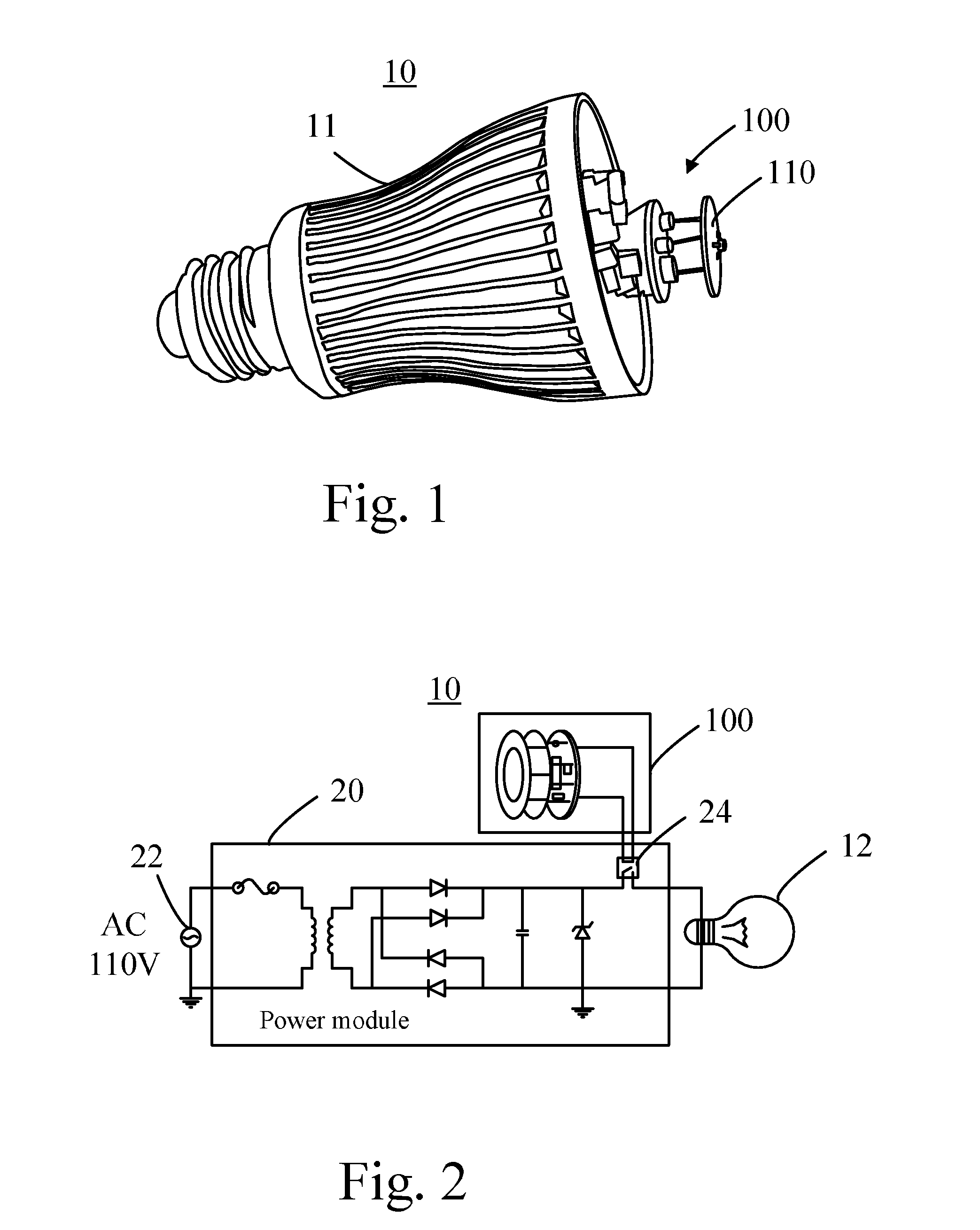
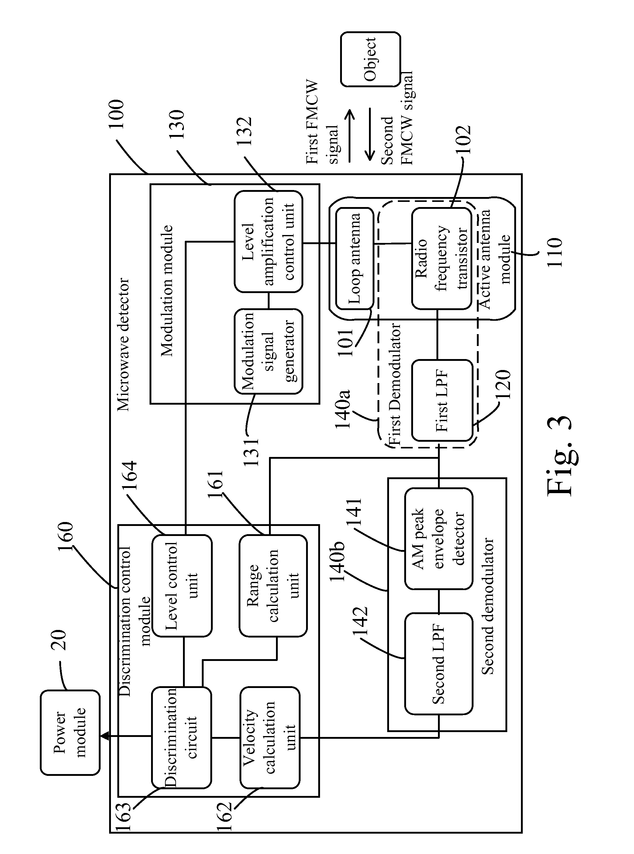
[0040]Please refer to FIG. 1 and FIG. 2. FIG. 1 illustrates a lighting device 10 according to an embodiment of the present invention. FIG. 2 is a functional block diagram showing the lighting device 10. The lighting device 10 comprises a lamp body 11, a light source 12, a microwave sensor 100, and a power module 20. The light source 12 may be a light emitting diode (LED). The microwave sensor 100 integrates a conventional active antenna and a conventional radio frequency (RF) module for calculating a range between the microwave sensor 10...


PUM


Abstract

A lighting device includes a microwave sensor for adjusting its sensing range based on a range gate selected from multiple range gates. An active antenna module transmits first FMCW signal toward a target based on the selected range gate and for receiving second FMCW signal reflected from the target. The microwave sensor demodulates the first FMCW signal and the second FMCW signal to generate beat frequency signal. Then another demodulator demodulates the beat frequency signal to generate Doppler signal. The microwave sensor calculates a range between the microwave sensor and the target based on the beat frequency signal, calculates velocity of the target according to frequency of the Doppler signal, and determine whether to generate triggering signal according to the calculated velocity and the calculated range, when the object located within the range gate. The power module enables a lamp based on the triggering signal.

Description

CROSS REFERENCE TO RELATED APPLICATION[0001]This application claims priority to Taiwan Application Serial Number 102132290, filed on Sep. 6, 2013, which are herein incorporated by reference.BACKGROUND OF THE INVENTION[0002]1. Field of the Invention[0003]The present invention relates to a lighting device, and more particularly, to a lighting device has a microwave detection function for sensing range and velocity of a moving target.[0004]2. Description of the Prior Art[0005]According to modern intelligent smart homecare and energy-saving requirements, a switch of a lamp or strength of illumination of a lamp in most of lighting devices is designed with a power-saving and energy-saving structure. A common low-power miniature sensor is divided into two types—an infrared sensor and a microwave sensor. The infrared sensor is an electronic device which senses a moving object. The infrared sensor senses movement of the object with variation of infrared ray emitted by a human being. The micr...

Claims


Application Information

Patent Timeline
Patent Type & Authority Applications(United States)
IPC IPC(8): G01S13/86
CPCG01S13/86F21V23/045F21V23/0471F21K9/23G01S7/03G01S7/35G01S13/345G01S13/56G01S13/584H05B47/115Y02B20/40
Inventor CHANG, CHI-HOSUNG, YUN-CHUNHSU, MING-TSUNGHUANG, JEN-CHIHLU, GUO-ZHONGTSAO, PING-CHANG
Owner U&U ENG
Why Eureka
Try Eureka