Measuring apparatus for three-dimensional profilometry and method thereof

a three-dimensional profilometry and measuring apparatus technology, applied in the field of three-dimensional profilometry, can solve the problems of reducing depth resolution and accuracy accordingly, affecting the inspection efficiency of the image, and affecting the quality of the image,

Active Publication Date: 2015-03-12
NAT TAIWAN UNIV
View PDF8 Cites 30 Cited by
  • Summary
  • Abstract
  • Description
  • Claims
  • Application Information

AI Technical Summary

Benefits of technology

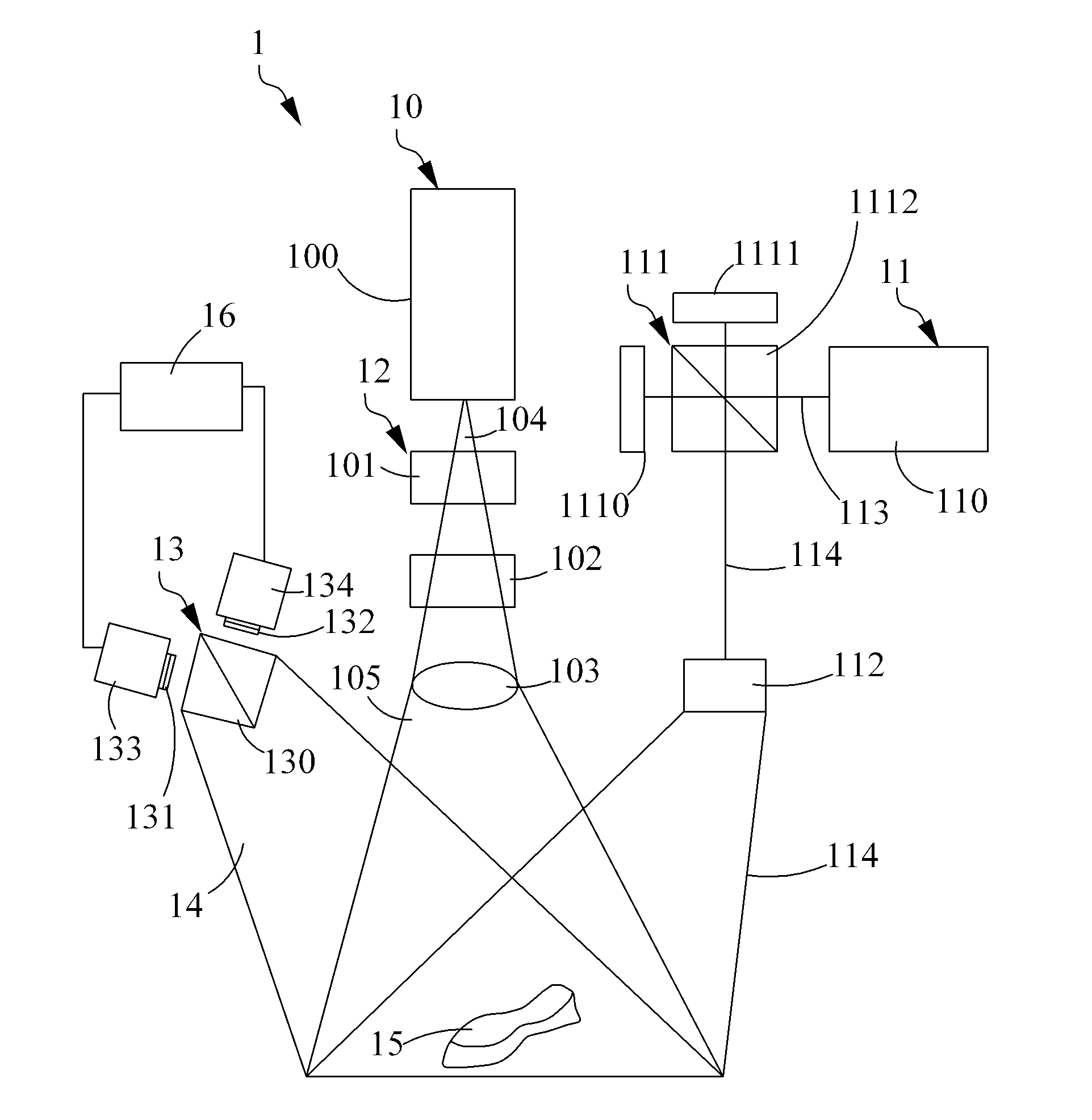
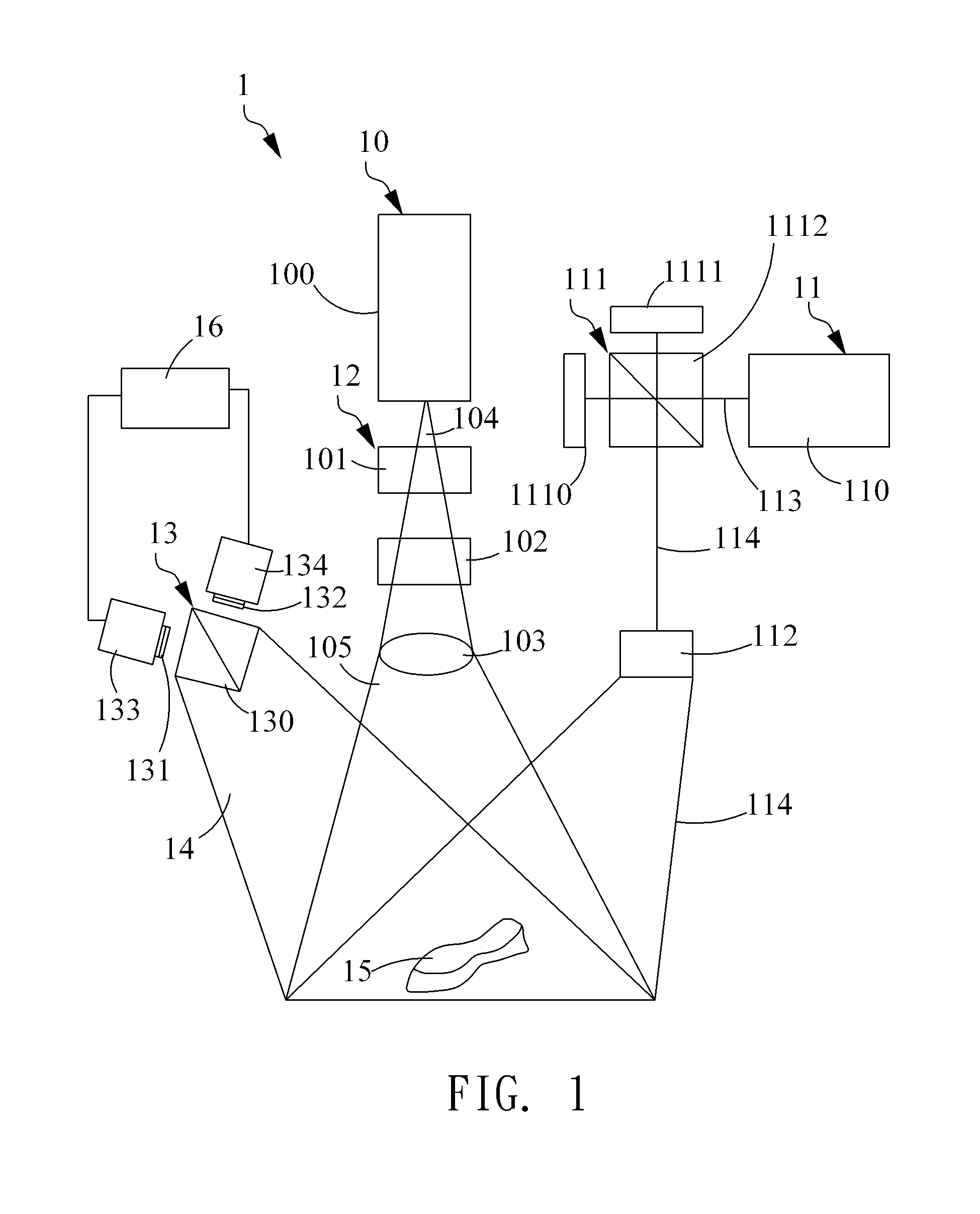
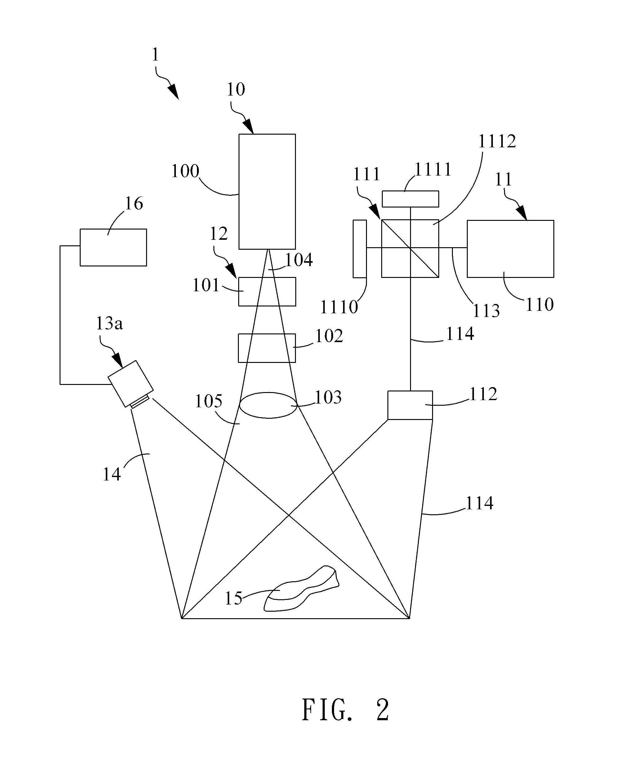
[0009]The present invention provides a method and apparatus of three-dimensional profilometry, which synchronously or asynchronously projects a first structured light having randomly distributed pattern such as speckle patterns and being formed by a first light wavelength, and a second structured light such as sinusoidal structured light having structured fringe patterns and being formed by a second light wavelength onto an object underlying test, acquires the deformed structured light reflected from the object by a image acquiring module thereby forming a random-speckle image and a structured-fringe one having scope of field the

Problems solved by technology

However, in the phase-shifting profilometry, since it is necessary to acquire a plurality of interference images for analyzing the surface profile of the object, it needs time-resolved multiple shifting operation to determine the tested surface of the object, its inspection efficiency is generally not desirable as other one-shot types of surface profiling methods, such as Fourier transform profilometry (FTP), which can only reply on single deformed structured pattern acquisition to complete the phase retrieval.
Although the gray scale coding combined with phase-shifting technique can be utilized to detect surface profile without being affected by the above mentioned phase ambiguity, when it comes to increase the depth resolution of

Method used


Image

  • Measuring apparatus for three-dimensional profilometry and method thereof
  • Measuring apparatus for three-dimensional profilometry and method thereof
  • Measuring apparatus for three-dimensional profilometry and method thereof

Examples


examples

[0074]In the following description, an example shown the comparing result between the combination of speckle interferometry and four-step phase-shifting interferometry, and speckle interferometry or phase-shifting interferometry is described hereinafter. Please refer to FIGS. 13 and 14, in which FIG. 13 represents a random-speckle image acquired from an object having a step height of 5.5 mm, while FIG. 14 represents a structured fringe image acquired from the same object underlying test. In FIG. 15, it illustrates an analysis result by using four-step phase-shifting analysis on the acquired fringe image. It is clear that the surface depth of the inspection result is −2.6 mm at the inspecting positions, which is opposite to the real step height of the object. The error is caused due to the known 2Nπ ambiguities if the phase information corresponding to the step height of the object is more than the period corresponding to the width of the fringe. Meanwhile, if the surface profile is ...


PUM


Abstract

The present invention provides measuring apparatus and method for three-dimensional profilometry of an object, wherein a random-speckle beam and a structured fringe beam are projected onto the object and reflected therefrom for forming deformed random-speckle beam and structured fringe beams that are separately acquired by an image acquiring device thereby obtaining a random-speckle image utilized to determine an absolute phase information of each position on the surface of the object, and a structured fringe image utilized to determine a relative phase information for each position of the surface of the object. Each absolute phase information and each relative phase information corresponding to each position are converted into an absolute depth and a relative depth, respectively. Finally, the depth information of each position on the surface of the object is calculated by combining the corresponding absolute depth and the relative depth whereby the surface profile of the object can be established.

Description

FIELD OF THE INVENTION[0001]The present invention provides a three-dimensional profilometry and more particularly, a method and apparatus for three-dimensional profilometry, wherein an absolute phase information and a relative phase information obtained by analyzing a random-speckle image and a structured fringe image corresponding to a surface of an object are utilized to determine depths of inspection positions on the surface of the object such that a full-field surface profilometry with highly superior accuracy and a larger measurable range of the object's surface depth can be achieved.BACKGROUND OF THE INVENTION[0002]Three-dimensional profilometry is a common surface profile measuring technology for analyzing the quality of various manufacturing or other kind of processes in the modern time. Generally, the commonly used three-dimensional structured light projection profilometry includes phase-shifting, gray-code, binary-code and random-speckle projecting techniques.[0003]In the ...

Claims


Application Information

Patent Timeline
IPC IPC(8): G01B11/25H04N9/31G06T7/00H04N13/02
CPCG01B11/254G06T7/0057H04N9/31H04N13/0239G06T7/521G01B11/2531H04N13/254
Inventor CHEN, LIANG-CHIAHSIEH, CHUNG-ANWENG, MING-XUAN
Owner NAT TAIWAN UNIV
Why Eureka
Try Eureka