Moisture removal device, lighting device for mounting on vehicle, and light source lighting device
- Summary
- Abstract
- Description
- Claims
- Application Information
AI Technical Summary
Benefits of technology
Problems solved by technology
Method used
Image
Examples
embodiment 1
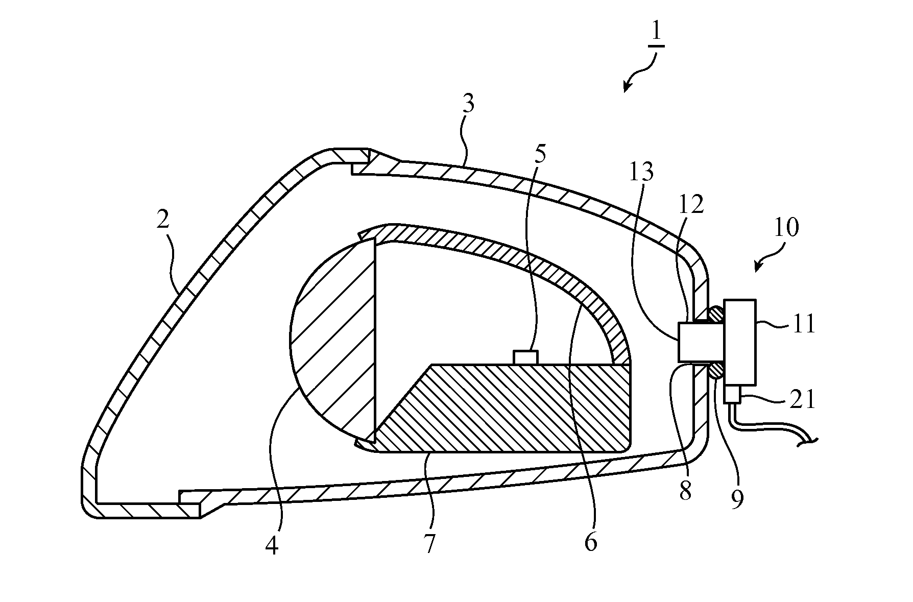
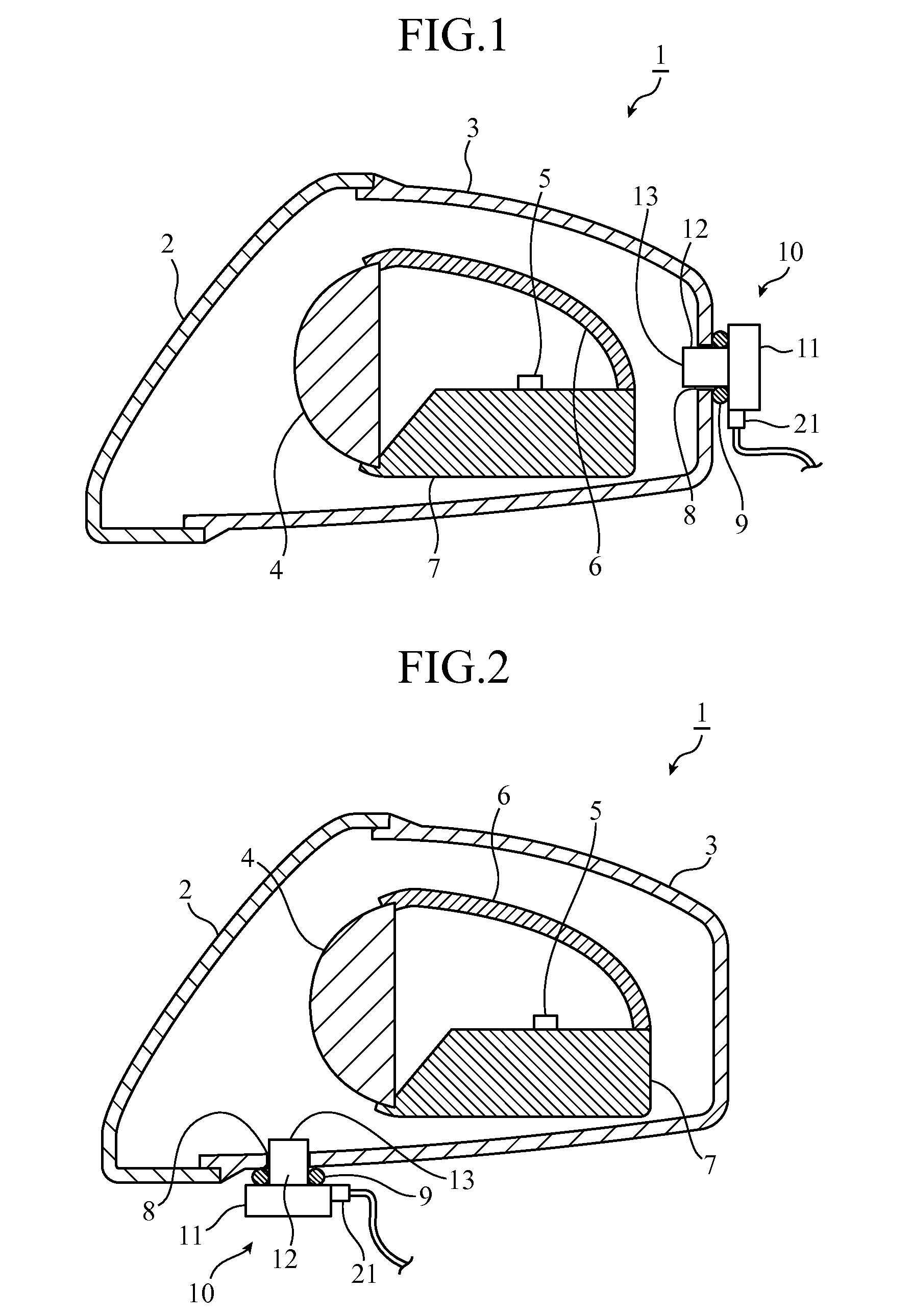
[0053]As shown in FIG. 1 and FIG. 2, a headlamp 1 that is one of light assemblies for on-vehicle use (on-vehicle lighting fixtures), is configured with a housing that is formed of a front lens 2 and a casing 3, and that accommodates a projection lens 4 placed on an optical axis extending in a vehicle front-rear direction, an LED (light source) 5 disposed backward from the projection lens 4, a mirror reflector 6 that reflects light from the LED 5 toward the projection lens 4, and a heat sink 7 on which the LED 5 is placed. In the configuration example in FIG. 1, a mounting hole 8 is formed on a rear surface of the casing 3 and a moisture removal device 10 is mounted to the mounting hole 8. In the configuration example in FIG. 2, the mounting hole 8 is formed on a lower surface of the casing 3 and the moisture removal device 10 is mounted thereto.
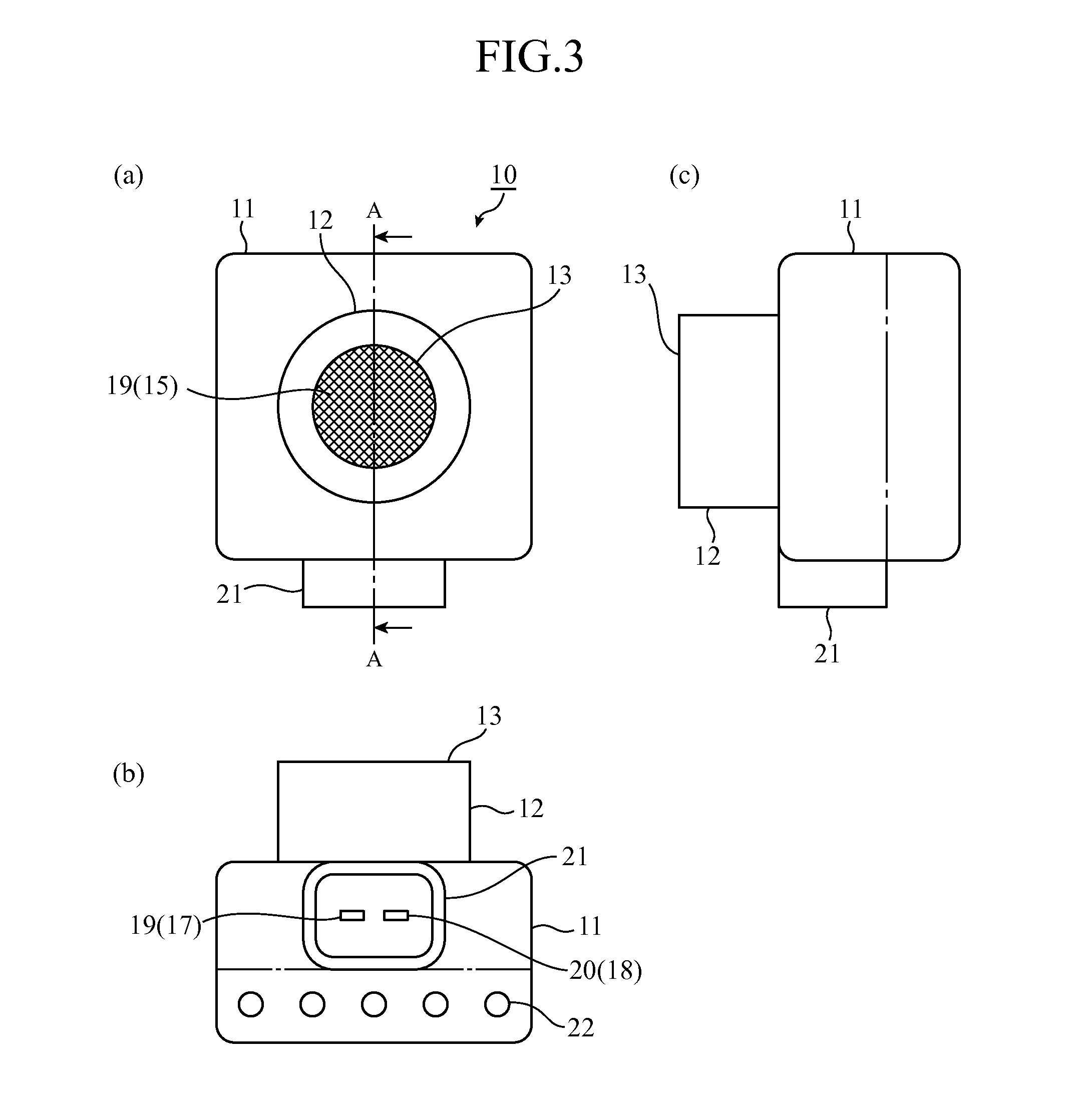
[0054]External appearances of the moisture removal device 10 are shown in FIG. 3, and a cross-sectional view taken along A-A line therein is...
embodiment 2
[0092]FIG. 7 is a diagram illustrating a fixing method of a headlamp 1 and a moisture removal device 10 according to Embodiment 2, and shows an example of their configurations to be fixed by screw. Note that, in FIG. 7, the same reference numerals are given for the same or equivalent parts as in FIG. 1 to FIG. 6, so that their description is omitted here.
[0093]In the case illustrated in the figure, a configuration example is shown in which screw holes (fixing portions) 40 are formed at four locations around the mounting hole 8 formed on the casing 3 of the headlamp 1. In the moisture removal device 10 to be mounted to the headlamp 1 with the above configuration, screw passing holes (fixing members) 41 are formed at four locations on the housing 11. By means of four screws (fixing members) 42, the housing 11 of the moisture removal device 10 is fixed to the casing 3 of the headlamp 1. Further, in order to prevent water from intruding into the headlamp 1 through a gap between the moun...
embodiment 3
[0098]FIG. 8 is a diagram illustrating a fixing method of a headlamp 1 and a moisture removal device 10 according to Embodiment 3, and shows an example of their configurations to be fixed by a bayonet mechanism. Note that, in FIG. 8, the same reference numerals are given for the same or equivalent parts as in FIG. 1 to FIG. 6, so that their description is omitted here.
[0099]Cutout portions 43 are formed at two locations of the mounting hole 8 formed on the casing 3 of the headlamp 1, and projection portions 44 to be fitted in the cutout portions 43 are protrusively formed at two locations on the cylindrical convex portion 12 of the moisture removal device 10. Then, the cylindrical convex portion 12 is inserted into the mounting hole 8 while the cutout portions 43 and the projection portions 44 are kept fitted together. After completion of insertion, the moisture removal device 10 is rotated about the center axis of the cylindrical convex portion 12 to thereby latch the projection po...
PUM
| Property | Measurement | Unit |
|---|---|---|
| Force | aaaaa | aaaaa |
| Electrical conductor | aaaaa | aaaaa |
| Electric potential / voltage | aaaaa | aaaaa |
Abstract
Description
Claims
Application Information
 - R&D
- Intellectual Property
- Life Sciences
- Materials
- Tech Scout
- Unparalleled Data Quality
- Higher Quality Content
- 60% Fewer Hallucinations
Browse by: Latest US Patents, China's latest patents, Technical Efficacy Thesaurus, Application Domain, Technology Topic, Popular Technical Reports.
© 2025 PatSnap. All rights reserved.Legal|Privacy policy|Modern Slavery Act Transparency Statement|Sitemap|About US| Contact US: help@patsnap.com


