Device and Method for Calorimetrically Measuring Sorption Processes
- Summary
- Abstract
- Description
- Claims
- Application Information
AI Technical Summary
Benefits of technology
Problems solved by technology
Method used
Image

Examples
first embodiment
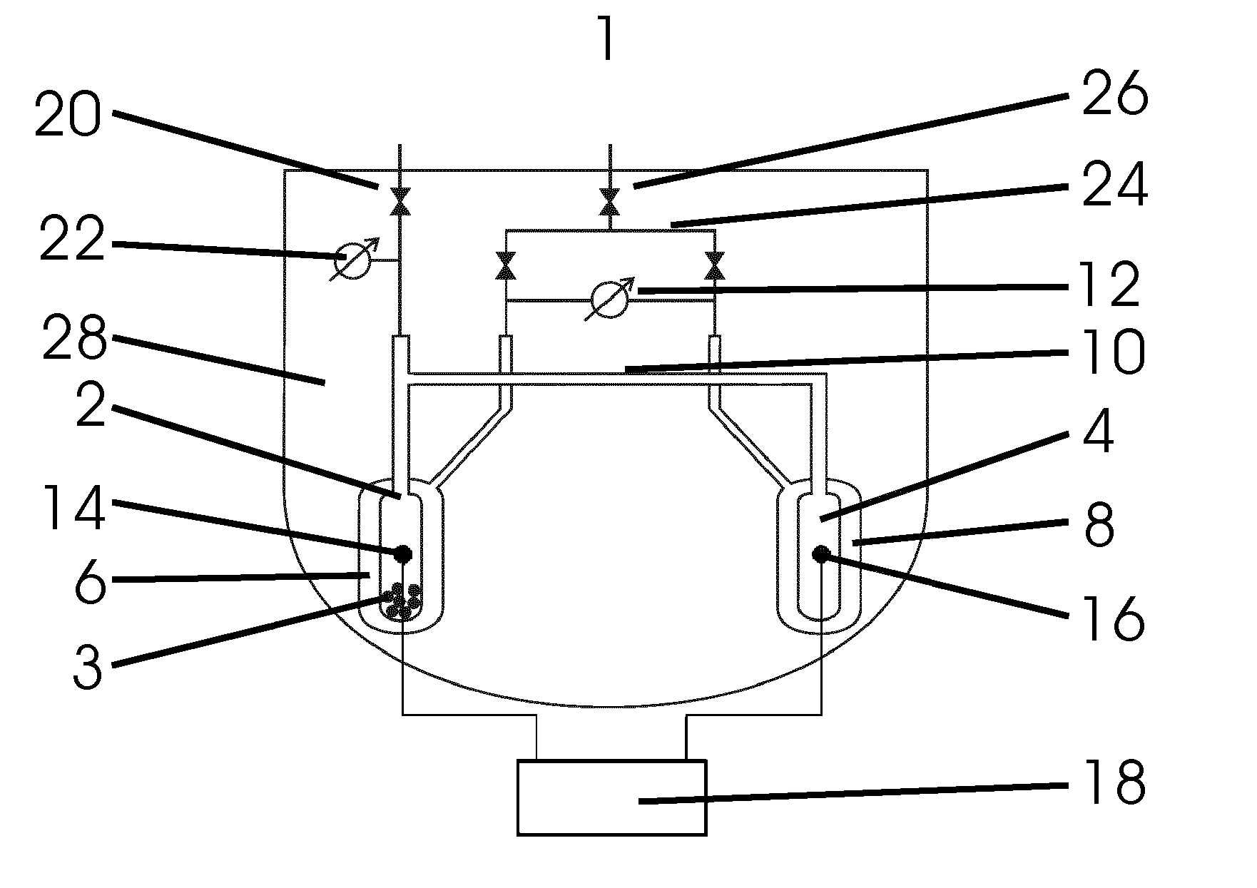
[0049]a device 1 shown in FIG. 1 for calorimetrically measuring sorption processes has a sorption cell 2 for receiving a sample 3 as well as a reference cell 4, wherein the sorption cell 2 and the reference cell 4 are arranged symmetrically with respect to each other inside the device 1.
[0050]Respectively one gas connection 10 is arranged on the upper end of the sorption cell 2 and the reference cell 4, which connects the interior spaces of the both measurement cells 2, 4 so that sorption gas can be conducted simultaneously to both measurement cells 2, 4 and there is a pressure equalization in both measurement cells 2, 4.
[0051]The sorption gas is introduced via a supply line with shut-off valve 20, which leads along the main axis of the sorption cell 2 from inside the device 1 to the outside and is connected with the gas connection 10 above the sorption cell 2. The valve arranged on the upper end of the supply line with shut-off valve 20 seals the equipment in a gas-tight manner and...
third embodiment
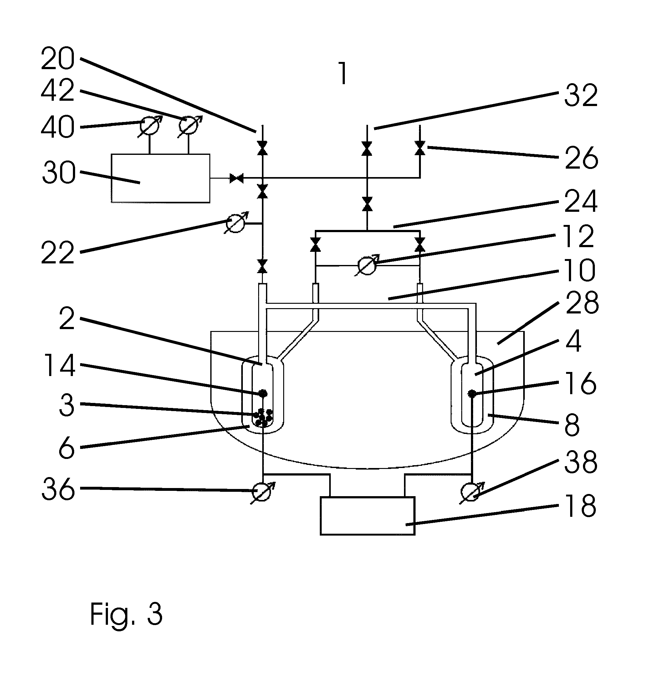
[0073]FIG. 3 shows the invention. In the subsequent description, only the differences to the embodiment of the device 1 shown in FIG. 1 are covered.
[0074]The device 1 for calorimetrically measuring sorption processes shown here has a gas storage tank 30, which is connected in a blockable manner with respect to the rest of the device 1 by means of a line with a valve. A pressure measuring device 40 and a temperature measuring device 42 of the gas storage tank are arranged on the gas storage tank 30.
[0075]The supply line with shut-off valve 20, the device for filling with reference gas 26 and the blockable inlet 32 are connected with the gas storage tank 30 via a line in a blockable way. Starting from this line, two additional blockable lines lead to the sorption cell 2 and to the measurement gas volume 6 as well as to the reference gas volume 8.
[0076]Another difference to the embodiments shown above is the volume of the adiabatic vessel 28. In this embodiment of the invention, it no ...
PUM
 Abstract
Description
Claims
Application Information