Centrifuge with automatic sampling and control and method thereof

a centrifuge and automatic technology, applied in centrifuges, centrifugal force sediment separation, separation processes, etc., can solve the problems of increasing operating costs, manual sampling and control input not responsive,

Active Publication Date: 2015-03-12
DERRICK CORP
View PDF24 Cites 30 Cited by
  • Summary
  • Abstract
  • Description
  • Claims
  • Application Information

AI Technical Summary

Benefits of technology

[0005]According to aspects illustrated herein, there is provided a centrifuge for centrifuging a slurry, including: a bowl driven by a bowl drive motor; a screw conveyor driven by a screw conveyor drive motor; a pump driven by a pump motor; a bowl variable frequency drive unit (VFD) operatively arranged to drive the bowl drive motor; a conveyor VFD operatively arranged to drive the screw conveyor drive motor; a pump VFD operatively arranged to drive the pump drive motor; a first analysis assembly connected to a first section of pipe connecting the pump and the bowl; and at least one computer electrically connected to the bowl VFD, the conveyor VFD, the pump VFD, and the first analysis assembly. The first analysis assembly is configured to automatically sample a slurry pumped through the first section of pipe and automatically transmit first data, characterizing the slurry, to the at least one computer. The at least one computer is configured to calculate respective control schemes for the bowl VFD, the conveyor VFD and the pump VFD using the first data and transmit respective control signals to the bowl VFD, the conveyor VFD and the pump VFD to operate the bowl VFD, the conveyor VFD and the pump VFD according to the respective control schemes.
[0006]According to aspects illustrated herein, there is provided a centrifuge for centrifuging a slurry, including: a bowl driven by a bowl drive motor; a screw conveyor driven by a screw conveyor drive motor; a pump driven by a pump motor; a bowl variable frequency drive unit (VFD) operatively arranged to drive the bowl drive motor; a conveyor VFD operatively arranged to drive the screw conveyor drive motor; a pump VFD operatively arranged to drive the pump drive motor; a first analysis assembly; and at least one computer electrically connected to the bowl VFD, the conveyor VFD, the pump VFD, and the first analysis assembly. The first analysis assembly is configured to automatically sample a liquid effluent discharged from the centrifuge and automatically transmit first data, characterizing the liquid effluent, to the at least one computer. The at least one computer is configured to calculate respective control schemes for the bowl VFD, the conveyor VFD and the pump VFD using the first data and transmit respective control signals to the bowl VFD, the conveyor VFD and the pump VFD to operate the bowl VFD, the conveyor VFD and the pump VFD according to the respective control schemes.
[0007]According to aspects illustrated herein, there is provided a centrifuge for centrifuging a slurry, including: a bowl driven by a bowl drive motor; a screw conveyor driven by a screw conveyor drive motor; a pump driven by a pump motor; a bowl variable frequency drive unit (VFD) operatively arranged to drive the bowl drive motor; a conveyor VFD operatively arranged to drive the screw conveyor drive motor; a pump VFD operatively arranged to drive the pump drive motor; a first analysis assembly connected to a section of pipe connecting the pump and the bowl; a second analysis assembly; and at least one computer electrically connected to the bowl VFD, the conveyor VFD, the pump VFD, and the first and second analysis assemblies. The first analysis assembly is configured to automatically sample a slurry pumped through the first section of pipe and automatically transmit first data, characterizing the slurry, to the at least one computer. The second analysis assembly is configured to automatically sample a liquid effluent discharged from the centrifuge and automatically transmit first data, characterizing the liquid effluent, to the at least one computer. The at least one computer is configured to calculate respective control schemes for the bowl VFD, the conveyor VFD and the pump VFD using the first and second data and transmit respective control signals to the bowl VFD, the conveyor VFD and the pump VFD to operate the bowl VFD, the conveyor VFD and the pump VFD according to the respective control schemes.
[0008]According to aspects illustrated herein, there is provided a method for centrifuging a slurry using a centrifuge including a bowl driven by a bowl drive motor, a screw conveyor driven by a screw conveyor drive motor, a pump driven by a pump motor, a bowl variable frequency drive unit (VFD) operatively arranged to drive the bowl drive motor, a conveyor VFD operatively arranged to drive the screw conveyor drive motor, a pump VFD operatively arranged to drive the pump drive motor, a first analysis assembly connected to a first section of pipe connecting the pump and the bowl, a second analysis assembly, and at least one computer electrically connected to the bowl VFD, the conveyor VFD, the pump VFD, and the first and second analysis assemblies, the method including: automatically sampling, using the first analysis assembly, a slurry pumped through the first section of pipe; automatically transmitting, using the first analysis assembly, first data, characterizing the slurry, to the at least one computer; automatically sampling, using the second analysis assembly, a liquid effluent discharged from the centrifuge; automatically transmitting, using the second analysis assembly, second data, characterizing the liquid effluent, to the at least one computer; calculating, using the at least one computer, respective control schemes for the bowl VFD, the conveyor VFD and the pump VFD using the first and second data; transmitting, using the at least one computer, respective control signals to the bowl VFD, the conveyor VFD and the pump VFD; and operating the bowl VFD, the conveyor VFD and the pump VFD according to the respective control schemes.

Problems solved by technology

The known method of manual sampling and control input is not responsive to current conditions in the centrifuge, since there is a time delay between obtaining samples and manually inputting set points due to the necessity for the operator to analyze the samples and determine proper control set points.
That is, the operator would be virtually dedicated to the sampling, analysis, and set point calculation noted above, which would greatly increase operating costs, since further personnel may be necessary to address operational needs that the operator cannot attend to.

Method used


Image

  • Centrifuge with automatic sampling and control and method thereof
  • Centrifuge with automatic sampling and control and method thereof
  • Centrifuge with automatic sampling and control and method thereof

Examples


Embodiment Construction

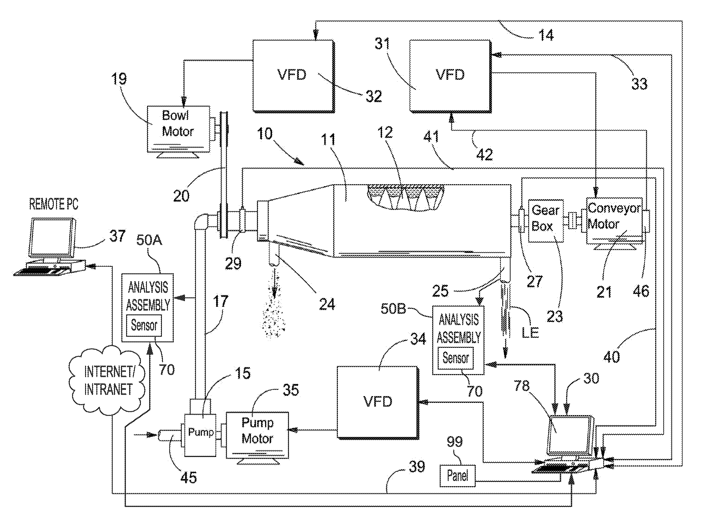
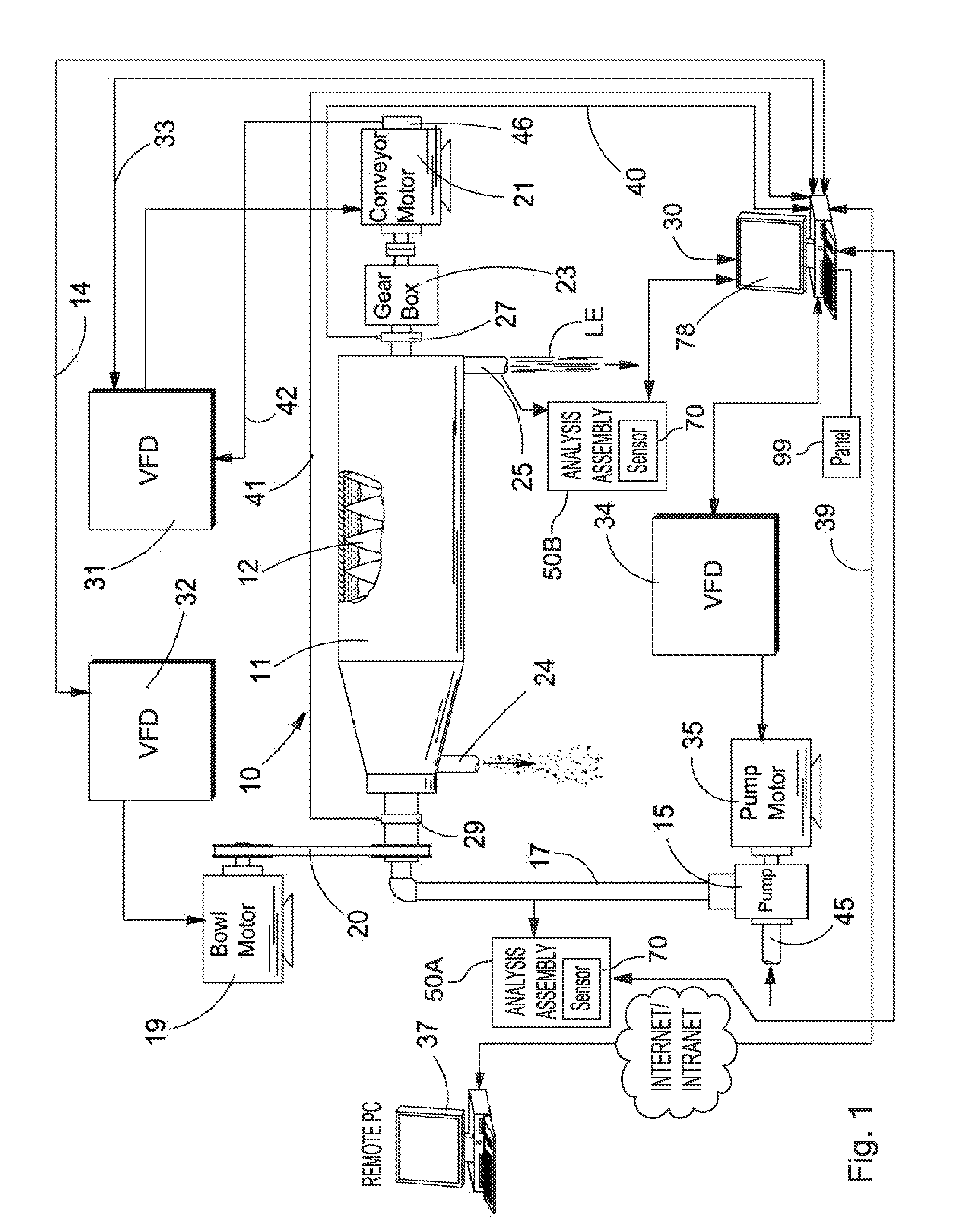
[0012]At the outset, it should be appreciated that like drawing numbers on different drawing views identify identical, or functionally similar, structural elements of the disclosure. It is to be understood that the disclosure as claimed is not limited to the disclosed aspects.

[0013]Furthermore, it is understood that this disclosure is not limited to the particular methodology, materials and modifications described and as such may, of course, vary. It is also understood that the terminology used herein is for the purpose of describing particular aspects only, and is not intended to limit the scope of the present disclosure.

[0014]Unless defined otherwise, all technical and scientific terms used herein have the same meaning as commonly understood to one of ordinary skill in the art to which this disclosure belongs. It should be understood that any methods, devices or materials similar or equivalent to those described herein can be used in the practice or testing of the disclosure.

[0015...


PUM

PropertyMeasurementUnit
feed densityaaaaaaaaaa
viscosityaaaaaaaaaa
turbidityaaaaaaaaaa

Abstract

A centrifuge including a bowl, a bowl drive motor, a screw conveyor, a screw conveyor drive motor, a pump, a pump motor, a bowl VFD to drive the bowl drive motor, a conveyor VFD to drive the screw conveyor drive motor, a pump VFD to drive the pump drive motor, an analysis assembly and a computer electrically connected to the bowl VFD, the conveyor VFD, the pump VFD, and the analysis assembly. The analysis assembly is configured to automatically sample slurry pumped into the bowl and automatically transmit data, characterizing the slurry, to the computer. The computer is configured to calculate control schemes for the bowl VFD, the conveyor VFD, and the pump VFD using the data and, transmit control signals to the bowl VFD, the conveyor VFD and the pump VFD to operate the bowl VFD, the conveyor VFD and the pump VFD according to the control schemes.

Description

CROSS-REFERENCE TO RELATED APPLICATIONS[0001]This application claims the benefit under 35 U.S.C. §119(e) of U.S. Provisional Patent Application No. 61 / 875,517, filed Sep. 9, 2013, which application is incorporated herein by reference in its entirety.FIELD OF THE INVENTION[0002]The present disclosure relates to a centrifuge with automatic sampling and analysis of a slurry pumped to the centrifuge and a liquid effluent discharged from the centrifuge, and automatic control of bowl, conveyor and pump motors.BACKGROUND OF THE INVENTION[0003]It is known to measure properties of a feed slurry and a liquid effluent stream for a centrifuge by analyzing samples taken by hand by an operator of the centrifuge. The analysis is then used to determine control parameters for operation of a centrifuge. For example, the operator obtains and analyzes the data to determine set points for the various motors in the centrifuge and then manually enters the set points into a control system for the centrifug...

Claims


Application Information

Patent Timeline
Patent Type & Authority Applications(United States)
IPC IPC(8): B04B9/10
CPCB04B9/10B04B11/02B04B13/00B04B1/2016B04B1/20
Inventor DERRICK, BRADLEY T.SCHWEC, MICHAEL J.
Owner DERRICK CORP
Why Eureka
Try Eureka