Joint stability device and method

Inactive Publication Date: 2015-03-12
SCHALLER MICHAEL PAUL
View PDF0 Cites 22 Cited by
  • Summary
  • Abstract
  • Description
  • Claims
  • Application Information

AI Technical Summary

Benefits of technology

The patent describes improved methods and devices for stabilizing joints in animals, particularly dogs. The invention addresses limitations of existing procedures such as difficulty in adjusting tension, lack of durability, and insufficient compliance. The invention provides a system that is adjustable, durable, and has an ideal amount of compliance. The invention also addresses challenges associated with using suture for repair procedures, such as break strength and deformation of the suture under high loads. The invention provides a solution to these challenges by using a woven stainless steel cable for stability. Overall, the invention provides a more effective and reliable method for stabilizing joints in animals.

Problems solved by technology

In the procedures described above, especially those which use a suture or similar material to provide stability, several limitations exist.
First these procedures may be difficult for the surgeon to adjust during or after the surgery to achieve the maximum potential benefit.
It may be difficult to apply the appropriate amount of tension to the suture while it is being clipped and then after it has been clipped it may be difficult to adjust the location of the clip on the suture.
This may result in either too much tension or not enough tension in the suture.
Once the screws have been drilled and secure it may be difficult to reposition the crown of the tibia.
Furthermore none of these procedures is easily adjustable after the surgical procedure.
Additionally, certain of these procedures may not have sufficient durability.
A repeat injury may occur in dogs especially in procedures where suture is used to support the knee as it is accepted that the suture breaks or dissolves after a period of 2-12 months.

Method used


Image

  • Joint stability device and method
  • Joint stability device and method
  • Joint stability device and method

Examples


Embodiment Construction

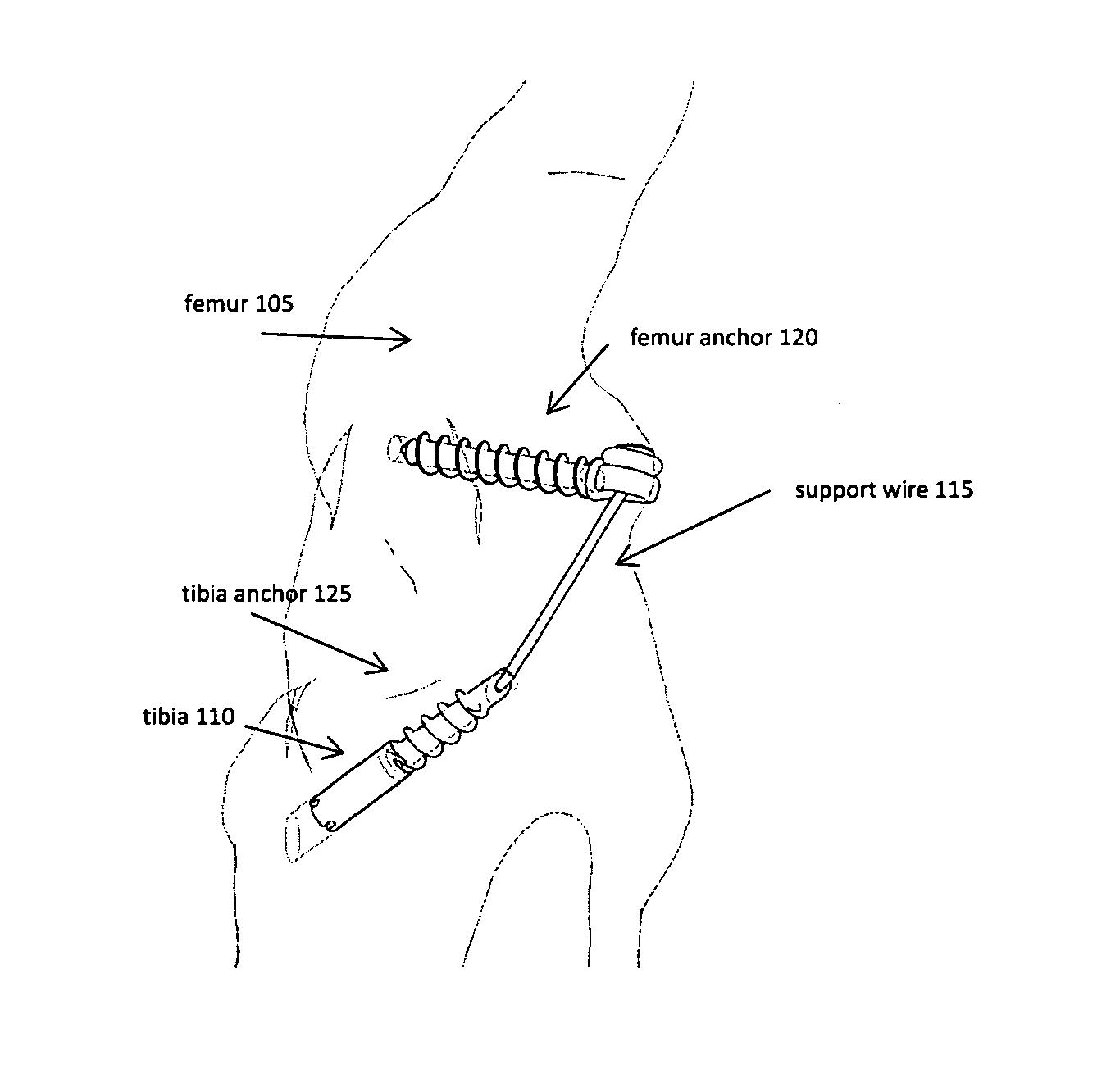
[0055]In FIG. 1 an exemplary apparatus is shown in an isometric view. A femur anchor 120 is shown extending from within the femur 105 and out of the bone profile. The femur anchor 120 has an eyelet or feature which is connected to the support wire 115 at a point which is external to the profile of the femur. A tibia anchor 125 is shown with the majority of the tibia anchor 125 within the profile of the tibia 110 as will be shown in FIG. 2. The support wire 115 is connected to the tibia anchor 125 and follows a path which may be considered similar to the patient's Cranial Cruciate Ligament (CrCL). In the following specification the term support wire is used interchangeable with the term linking element described within the claims of the invention.

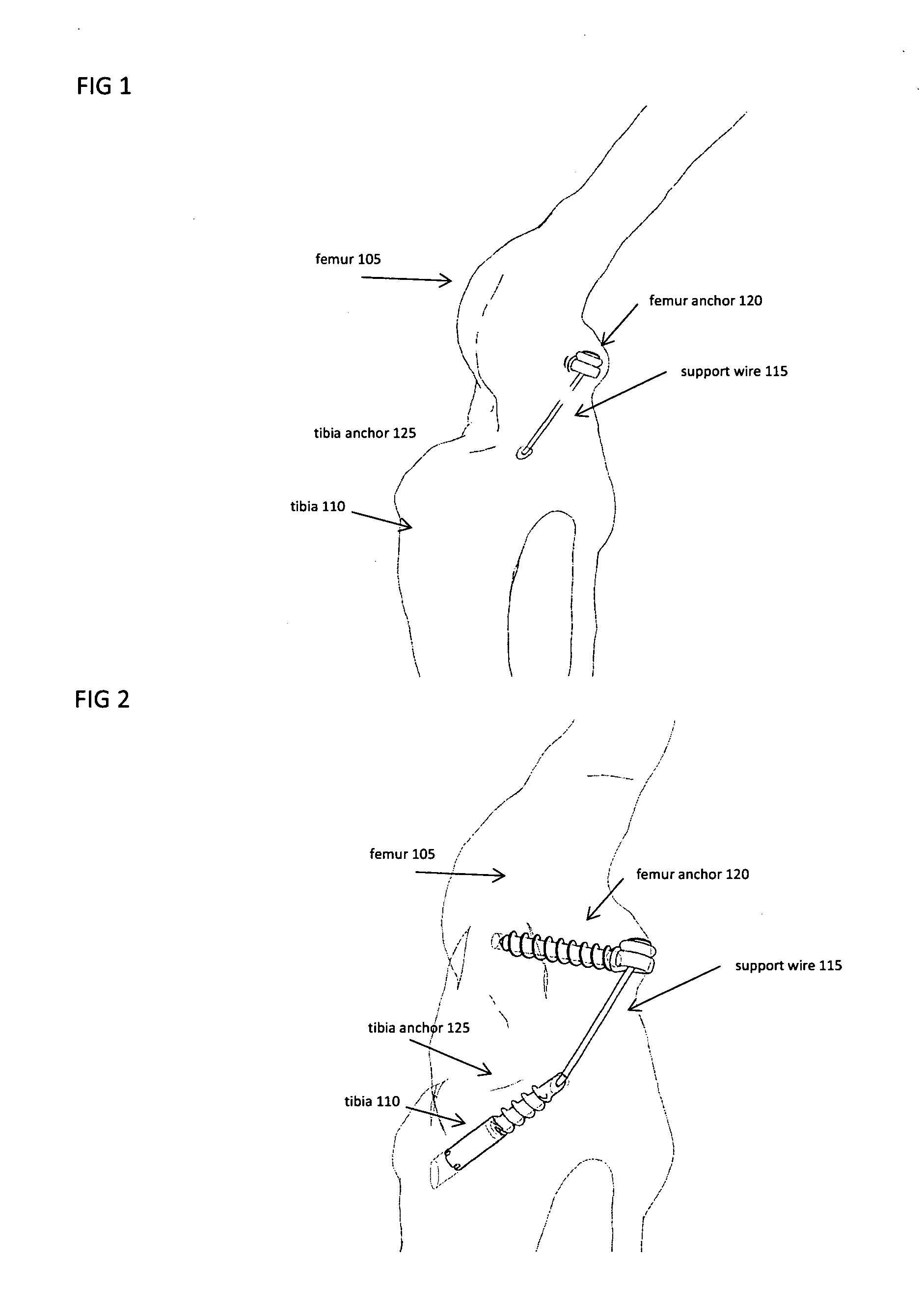
[0056]In FIG. 2 the same apparatus of FIG. 1. is shown in situ within the anatomy, with the stifle joint transparent so the location and geometry of the apparatus may be seen. In this embodiment, the femur anchor has an external screw thread...


PUM


Abstract

An apparatus for stabilizing a joint during orthopedic surgery. The apparatus includes a securing anchor which is rigidly attached to a bone, and a flexible cable which is connected to the anchor at a point which is external to the profile of the bone. The flexible cable is constructed of a substantially inelastic material such as stainless steel. The cable is connected to features and mechanisms which provide an apparent elasticity in the apparatus when the cable is placed in tension. Further the apparatus includes adjustment features and mechanisms which allow the user to adjust the amount of tension along the length of the cable. The bones may be the femur and tibia in the stifle joint of a dog.

Description

PRIORITY[0001]This patent application claims priority from provisional United States patent application:[0002]Application Ser. No. 61 / 876,758, filed Sep. 12, 2014, entitled, “Joint Stability Device and Method” naming Michael P Schaller as inventor.FIELD OF THE INVENTION[0003]The invention generally relates to joint surgery. More specifically, the invention relates to a method and device for stabilizing a joint in a canine stifle joint.BACKGROUND[0004]Injuries to ligaments are common in both humans and animals. In humans, there are roughly 250,000 surgeries to repair ACLs (anterior cruciate ligaments) each year. These injuries are typically caused by acute trauma where the ligament is over exerted and breaks. Treatment options generally consist of replacing the torn ACL with a new ligament either from the patient or from a cadaver. Canine's may have similar ligament injuries in their stifle joints, which is analogous to a knee joint. By contrast to humans, CrCL (cranial cruciate liga...

Claims


Application Information

Patent Timeline
IPC IPC(8): A61B17/04A61F2/08
CPCA61B17/0401A61F2/0811A61F2002/0852A61B2017/0441A61F2002/0817A61B2017/0427A61F2/08A61F2002/0829A61F2002/0835A61F2002/0841A61F2002/087A61F2002/0882A61F2002/0888A61F2220/0041A61F2250/0007A61F2250/0073A61B2017/567
Inventor SCHALLER, MICHAEL PAUL
Owner SCHALLER MICHAEL PAUL
Why Eureka
Try Eureka