Bearing apparatus for a wheel of vehicle

a technology for bearings and vehicles, applied in mechanical devices, rigid support of bearing units, transportation and packaging, etc., can solve the problems of deformation of the wheel mounting flange 58/b>, interference, and difficulty in miniaturizing and lightening the wheel hub, so as to increase the strength and durability of the wheel hub

Active Publication Date: 2008-11-18
NTN CORP
View PDF5 Cites 6 Cited by
  • Summary
  • Abstract
  • Description
  • Claims
  • Application Information

AI Technical Summary

Benefits of technology

[0008]It is an object of the present invention to provide a vehicle wheel bearing apparatus for a vehicle which increases the strength and durability of the wheel hub under rotary bending conditions as well as lightening it without changing the configuration and dimension of the wheel mounting flange and without causing surface run-out problems.

Problems solved by technology

However, since the mechanical strength of such a miniaturized wheel hub 51 itself nears the fatigue limit of the medium carbon steel forming the wheel hub 51, it is difficult to further proceed with the miniaturization and lightening of the wheel hub 51.
Although it is possible to reduce the generated stress by enlarging the dimension of the corner 61, by increasing the radius of curvature, it is also limited by interference due to the to be mounted brake rotor 57.
One problem is that the wheel mounting flange 58 is deformed by heat treatment in the high frequency induction hardening step.
The problem of surface run-out is also caused by thinning the wheel mounting flange 58.
This causes brake judder which impairs the driving stability and the driving feeling.

Method used


Image

  • Bearing apparatus for a wheel of vehicle
  • Bearing apparatus for a wheel of vehicle
  • Bearing apparatus for a wheel of vehicle

Examples


Embodiment Construction

[0029]The following description of the preferred embodiment(s) is merely exemplary in nature and is in no way intended to limit the invention, its application, or uses.

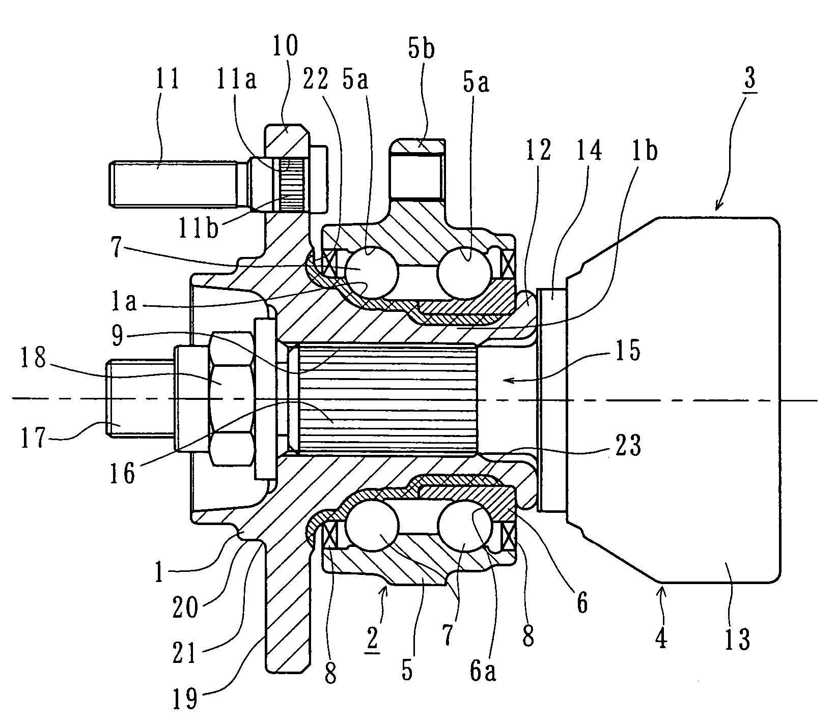
[0030]FIG. 1 shows a first embodiment of a vehicle wheel bearing apparatus of the present invention. In the description below, a term “outboard side” of the apparatus denotes a side which is positioned outside of the vehicle body and a term “inboard side” of the apparatus denotes a side which is positioned inside of the body when the bearing apparatus is mounted on the vehicle body.

[0031]The illustrated bearing apparatus is used for a vehicle driving wheel where a wheel hub 1 and a double row rolling bearing 2 are assembled as a unit. An outer joint member 4 of the constant velocity universal joint 3 is fitted on to the wheel hub 1 via serration engagement so as to transmit a torque therebetween.

[0032]The double row rolling bearing 2 comprises, as its main components, an outer member 5, the wheel hub 1, inner ring 6, ...


PUM


Abstract

A vehicle wheel bearing apparatus which can increase the strength and durability of the hub wheel under rotary bending conditions as well as lighten the apparatus without changing the configuration and dimension of the wheel mounting flange and without causing surface run-out has an outer member formed with double row outer raceway surfaces on its inner peripheral surface. An inner member is formed with double row inner raceway surfaces arranged opposite to the double row outer raceway surfaces. Double row rolling elements are freely rollably contained between the outer and inner raceway surfaces, respectively, of the outer and inner members. A wheel mounting flange is integrally formed with either one of the outer or inner members. At least one of the outer and inner members, on which the wheel mounting flange is formed, is heat treated and their raceway surfaces are hardened by quenching to a predetermined surface hardness.

Description

CROSS-REFERENCE TO RELATED APPLICATIONS[0001]This application claims priority to Japanese Patent Application No. 2003-166068, filed Jun. 11, 2003, which application is herein expressly incorporated by reference.FIELD OF THE INVENTION[0002]The present invention relates to a vehicle wheel bearing apparatus, such as an automobile, and, more particularly, to a bearing apparatus with a wheel hub having improved strength and durability under rotary bending conditions.BACKGROUND OF THE INVENTION[0003]The bearing apparatus for a vehicle wheel includes various types in accordance with applications for driven as well as driving wheels. For example, a conventional bearing apparatus for a vehicle driving wheel is shown in FIG. 5. The apparatus includes an inner member 50, a wheel hub 51, an inner ring 52, double row rolling elements 53 and 54, an outer member 55, and a constant velocity universal joint 56. The constant velocity universal joint transmits an engine output to the wheel hub 51. In ...

Claims


Application Information

Patent Timeline
IPC IPC(8): F16C19/08B60B27/00B60B35/14F16C19/18F16C33/62F16C33/64F16C33/78F16C35/063
CPCB60B27/00B60B27/0005B60B27/0026B60B27/0084B60B27/0094F16C19/185F16C19/186F16C33/64Y02T10/86F16C2326/02
Inventor HIRAI, ISAOTAKUBO, TAKAYASUYOSHIDA, KAZUHIKO
Owner NTN CORP
Why Eureka
Try Eureka