Oil-free air compressor for rail vehicles with air ventilation

a rail vehicle and air compressor technology, applied in the direction of machines/engines, liquid fuel engines, positive displacement liquid engines, etc., can solve the problems of increased maintenance and disposal expenditures, high heat development, oil fouling of pneumatically operated brake units on rail vehicles,

Inactive Publication Date: 2015-03-19
WABTEC HLDG CORP
View PDF22 Cites 14 Cited by
  • Summary
  • Abstract
  • Description
  • Claims
  • Application Information

AI Technical Summary

Problems solved by technology

In either mode of operation, friction during operation of the compressor leads to high heat development.
However, oil lubrication carries a risk that the lubricating oil, usually situated in the housing of the compressor unit in the case of a piston air compressor, can penetrate past the piston-cylinder interface and into the pneumatic system, which may result in oil fouling the pneumatically operated brake units on the rail vehicle.
This collection process leads to increased maintenance and disposal expenditures as well as to high oil consumption.
In addition to the foregoing difficulties, emulsion formations in the oil circuit of these oil-lubricated compressor units can occur if the oil-lubricated compressor units are used infrequently or for limited periods of time as during cold weather operation.
However, such light carrier structures frequently have a number of unfavorable natural frequencies that are close to the rotational speed of the air compressor of the pneumatic system which is arranged thereon.
Therefore, it is difficult to sufficiently observe the required specifications concerning permissible structure-born noise levels.

Method used


Image

  • Oil-free air compressor for rail vehicles with air ventilation
  • Oil-free air compressor for rail vehicles with air ventilation
  • Oil-free air compressor for rail vehicles with air ventilation

Examples


Embodiment Construction

[0034]For purposes of the description hereinafter, spatial orientation terms, as used, shall relate to the referenced embodiment as it is oriented in the accompanying drawing figures or otherwise described in the following detailed description. However, it is to be understood that the embodiments described hereinafter may assume many alternative variations and configurations. It is also to be understood that the specific components, devices, and features illustrated in the accompanying drawing figures and described herein are simply exemplary and should not be considered as limiting.

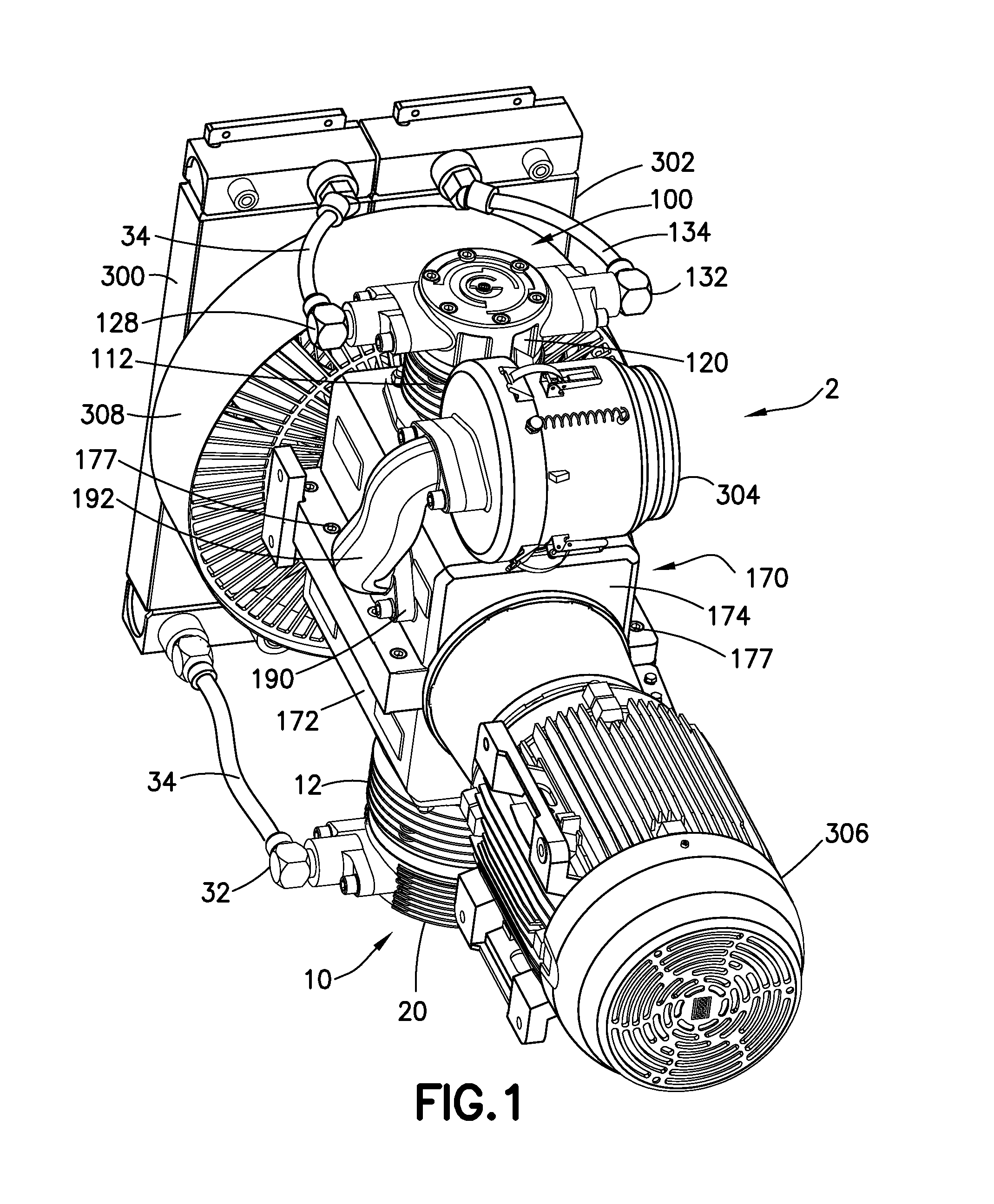
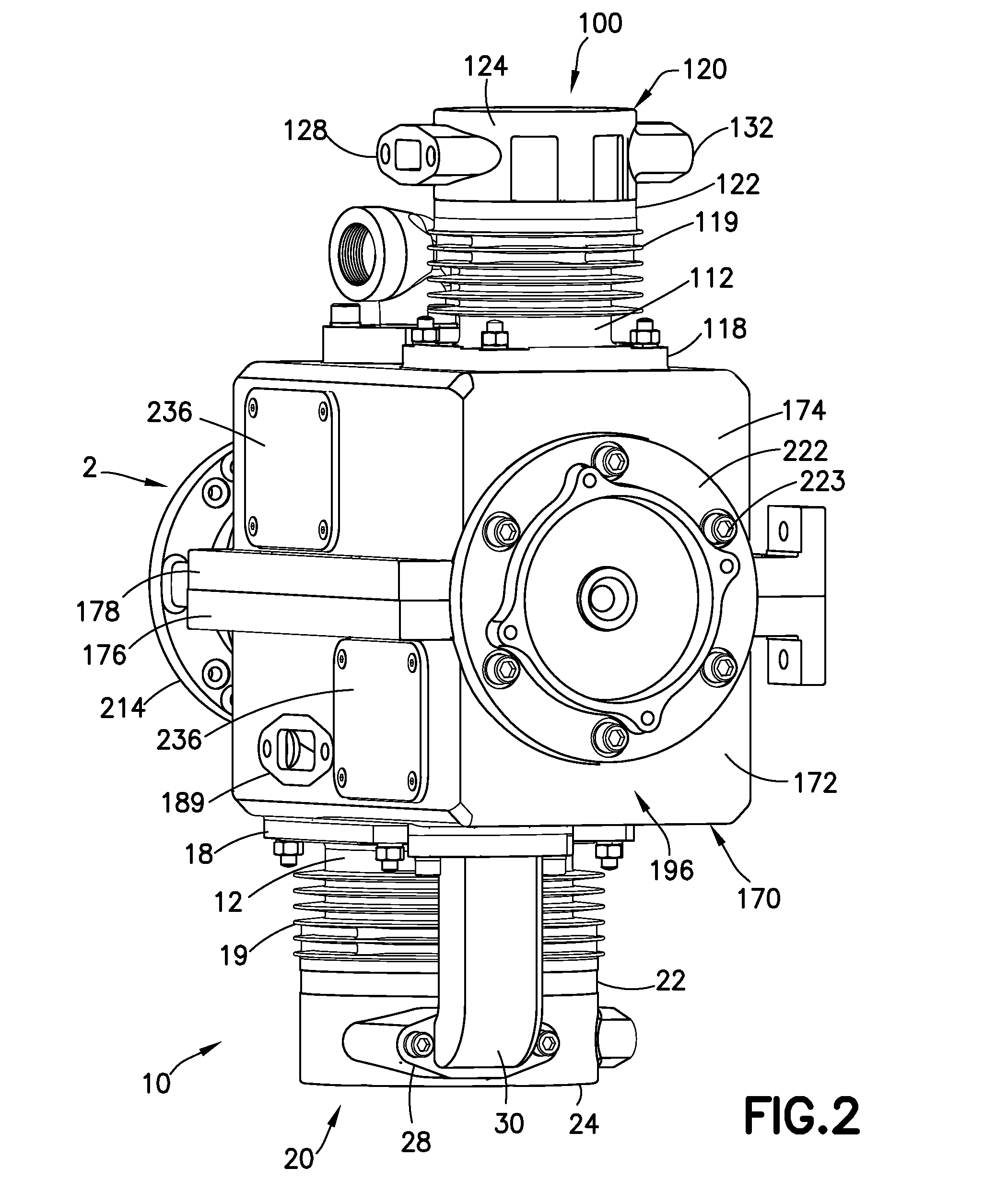
[0035]Referring to FIGS. 1-6, an air compressor 2 according to one embodiment is shown. As shown, the air compressor 2 is a multi-cylinder air compressor 2 comprising at least a first piston-cylinder 10 and a second piston-cylinder 100. The respective first and second piston-cylinders 10, 100 (hereinafter referred to as “first piston cylinder 10” and “second piston cylinder 100”) are supported by a compr...


PUM


Abstract

An oil-free compressor for a rail vehicle includes a multi-piece compressor housing, a first piston cylinder supported in a first opening in the compressor housing, a second piston cylinder supported in a second opening in the compressor housing, a multi-piece crankshaft assembly supported by the compressor housing, and an optionally filtering air plenum in fluid communication with the compressor housing interior to provide a volume of air to the compressor housing interior. The crankshaft assembly is linked to pistons of the first and second piston cylinders by respective connecting rods. The connecting rods connect to a wrist pin associated with each of the pistons, and the wrist pins are respectively supported by a dry lubricant bushing to the associated piston. The compressor housing may have a first housing portion and a second housing portion forming respective halves of the compressor housing.

Description

CROSS REFERENCE TO APPLICATIONS[0001]This application incorporates by reference U.S. patent application Ser. No. 13 / 350,980, filed Jan. 16, 2012 entitled “Oil-Free Air Compressor for Rail Vehicles”, which claims the benefit of U.S. Provisional Patent Application No. 61 / 437,333, filed Jan. 28, 2011, and entitled “Oil-Fee Air Compressor for Rail Vehicles”, the disclosures of which are incorporated herein in their entirety.BACKGROUND OF THE INVENTION[0002]1. Field of the Invention[0003]This disclosure relates to the field of air compressors adapted for use on rail vehicles for the purpose of supplying compressed air to pneumatic units associated with the rail vehicle and, in particular, to an oil-free air compressor on a rail vehicle with air ventilation; the oil-free air compressor is used for supplying compressed air to various pneumatic units associated with the rail vehicle.[0004]2. Description of Related Art[0005]Normally, a pneumatic system is provided for a rail vehicle by which...

Claims


Application Information

Patent Timeline
Patent Type & Authority Applications(United States)
IPC IPC(8): F04B39/00
CPCF04B39/0094F04B11/0091F04B25/005F04B27/005F04B27/02F04B39/121F04B39/00F04B53/18F04B39/127
Inventor KAPADIA, NEVILLE D.MOORE, ROLAND S.
Owner WABTEC HLDG CORP
Why Eureka
Try Eureka