Eureka AIR delivers breakthrough ideas for toughest innovation challenges, trusted by R&D personnel around the world.

Photovoltaic panel mounting rail with integrated electronics

Active Publication Date: 2015-03-19
LUMOS LSX
View PDF41 Cites 10 Cited by
  • Summary
  • Abstract
  • Description
  • Claims
  • Application Information

AI Technical Summary

Benefits of technology

The present invention is a photovoltaic mounting rail with integrated electronics. The rail is made of aluminum or plastic extrusion and has a unique design that allows for easy attachment of a photovoltaic panel. The rail has a mounting support and an outer sidewall with a service channel for electronic components. The size of the service channel can be adjusted to accommodate different electronic components. The technical effects of this design are efficient and flexible mounting of photovoltaic panels, easy connection to electronic components, and improved performance of the overall system.

Problems solved by technology

Larger central inverters, however, are sometimes too large or too heavy to hide for some solar projects.

Method used


Image

  • Photovoltaic panel mounting rail with integrated electronics
  • Photovoltaic panel mounting rail with integrated electronics
  • Photovoltaic panel mounting rail with integrated electronics

Examples


Embodiment Construction

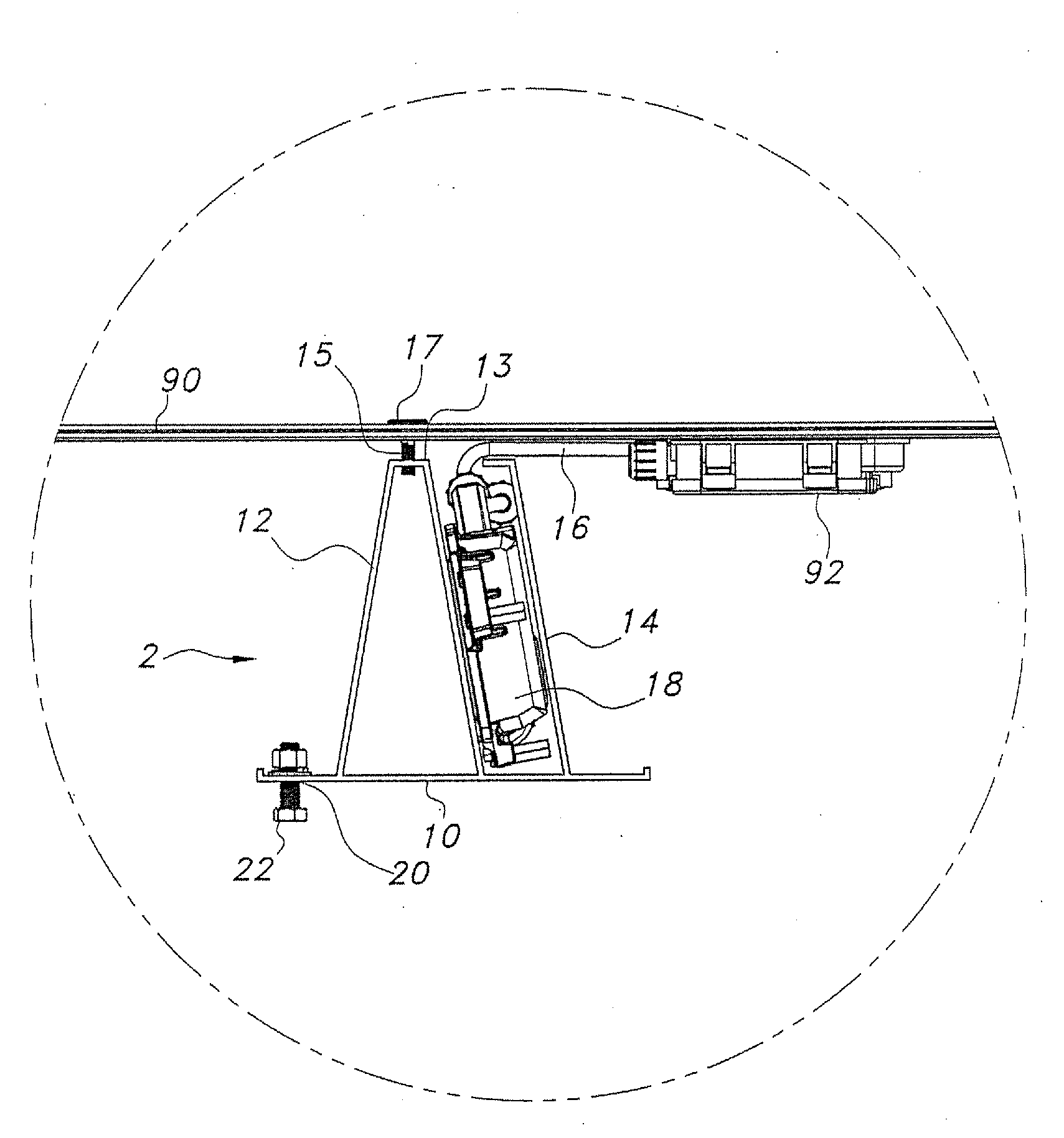
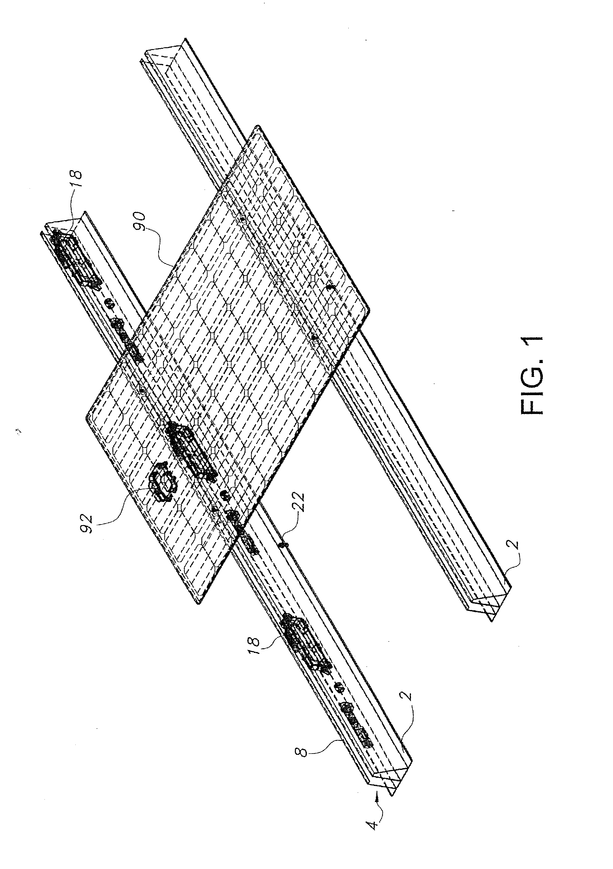
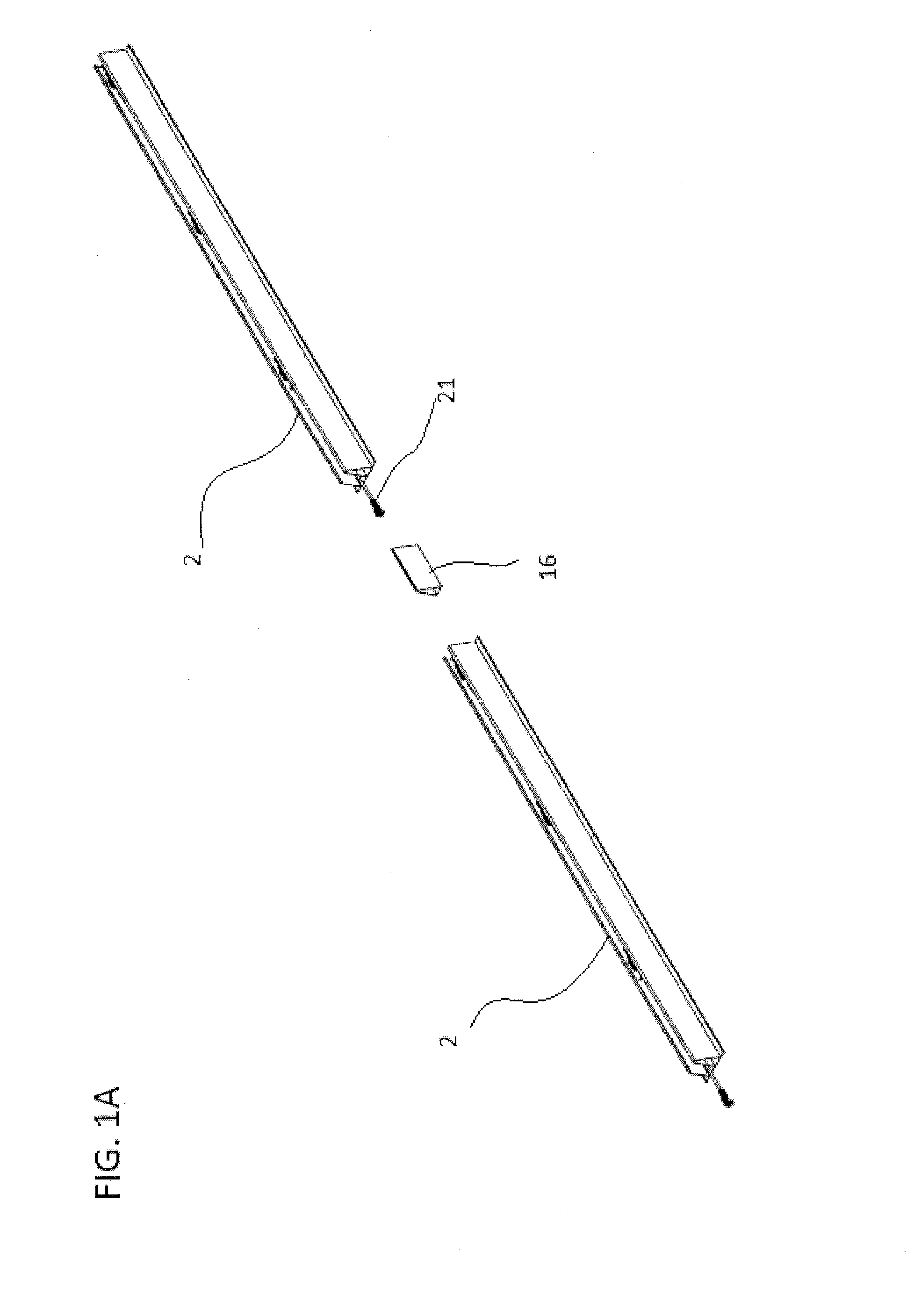
[0017]The present invention provides a rail for a solar racking system rail, which integrates electronic devices that are mounted directly onto the rail. Racking is the support structure onto which solar panels are mounted. The mounting system allows all of the electronic components to be located in one of the two rails. In order to achieve this, the photovoltaic panels can be secured to the mounting rails so that the junction boxes are all on the same side. The other rail provides support to an attachment point for the panel and would not have electronic components.

[0018]The mounting system for electronic components in a photovoltaic panel array as described herein provides several advantages. Mounting inverters / optimizers directly to a service channel in a rail system protects the electronics from weather and provides a neat and clean appearance. The arrangement of the present invention also provides for improved heat dissipation for the electronic components. Lastly, mounting the...


PUM


Abstract

A photovoltaic mounting rail that includes an elongate bottom wall, a mounting support, an outer sidewall and one or more electronic components. The mounting support extends upwardly from the bottom wall to a top wall and extends between the first and second ends of the rail. The outer sidewall extends upwardly from the bottom wall to a distal edge and also extends between the first and second ends of the bottom wall. The outer sidewall is spaced apart from the mounting support and defines a service channel between the outer sidewall and the mounting support. The rail is adapted for attachment of a photovoltaic panel with electronic devices to the top wall of the mounting support and the connection of the electronic devices to electronic components located within the service channel.

Description

[0001]This application claims priority from provisional application Ser. No. 61 / 878,974, filed on Sep. 17, 2013, which is incorporated herein in its entirety.FIELD OF INVENTION[0002]The invention relates to photovoltaic panel arrangements and, particularly to mounting electronics directly onto the rails of the solar racking system.BACKGROUND OF THE INVENTION[0003]Photovoltaic panels produce DC (direct current) voltage. In order to feed power to a home or city electrical grid, the voltage needs to be converted to AC (alternating current). Solar arrays typically have a large central inverter that converts the system voltage from DC to AC. Power flows from the solar modules to the inverters and then to the electrical grid.[0004]Often these large central inverters are placed in garages, sheds, hidden behind paneling, etc. to keep them protected and out of sight. Larger central inverters, however, are sometimes too large or too heavy to hide for some solar projects.[0005]Microinverters a...

Claims


Application Information

Patent Timeline
IPC IPC(8): H02S40/30H02S40/32H02S20/20F24J2/52
CPCH02S40/30H02S20/20H02S40/32F24J2/5245F24S25/30F24S25/617F24S25/65F24S2025/803H02S20/23Y02B10/10Y02E10/47Y02E10/50
Inventor FRANKLIN, SCOTTKLINGA, CHRISTOPHERRAFFERTY, BRIAN
Owner LUMOS LSX
Why Eureka
Eureka Blog
Learn More