Device for nebulizing a liquid

a liquid nebulizer and liquid technology, applied in the field of nebulizing liquid devices, can solve the problem of particularly low yield of such devices, and achieve the effect of increasing the frequency spectrum

Inactive Publication Date: 2015-03-19
ADLYNX
View PDF3 Cites 2 Cited by
  • Summary
  • Abstract
  • Description
  • Claims
  • Application Information

AI Technical Summary

Benefits of technology

[0042]Owing to these features, at the concurrent point, the frequencies of the wave fronts being close, an acoustic field of similar frequencies is created, which therefore includes the frequencies f2−n*(f2−f1), where n is an integer between 0 and f2 / (f2−f1). The frequency spectrum is thereby increased, along with the number of cavitation nuclei reached.
[0043]Unexpectedly, the beating created by the proximity of the waves increases locally, meaning that, at the concurrent point, the intensity of the wave fronts increases.

Problems solved by technology

The yield of such devices is particularly low.

Method used


Image

  • Device for nebulizing a liquid
  • Device for nebulizing a liquid

Examples


Embodiment Construction

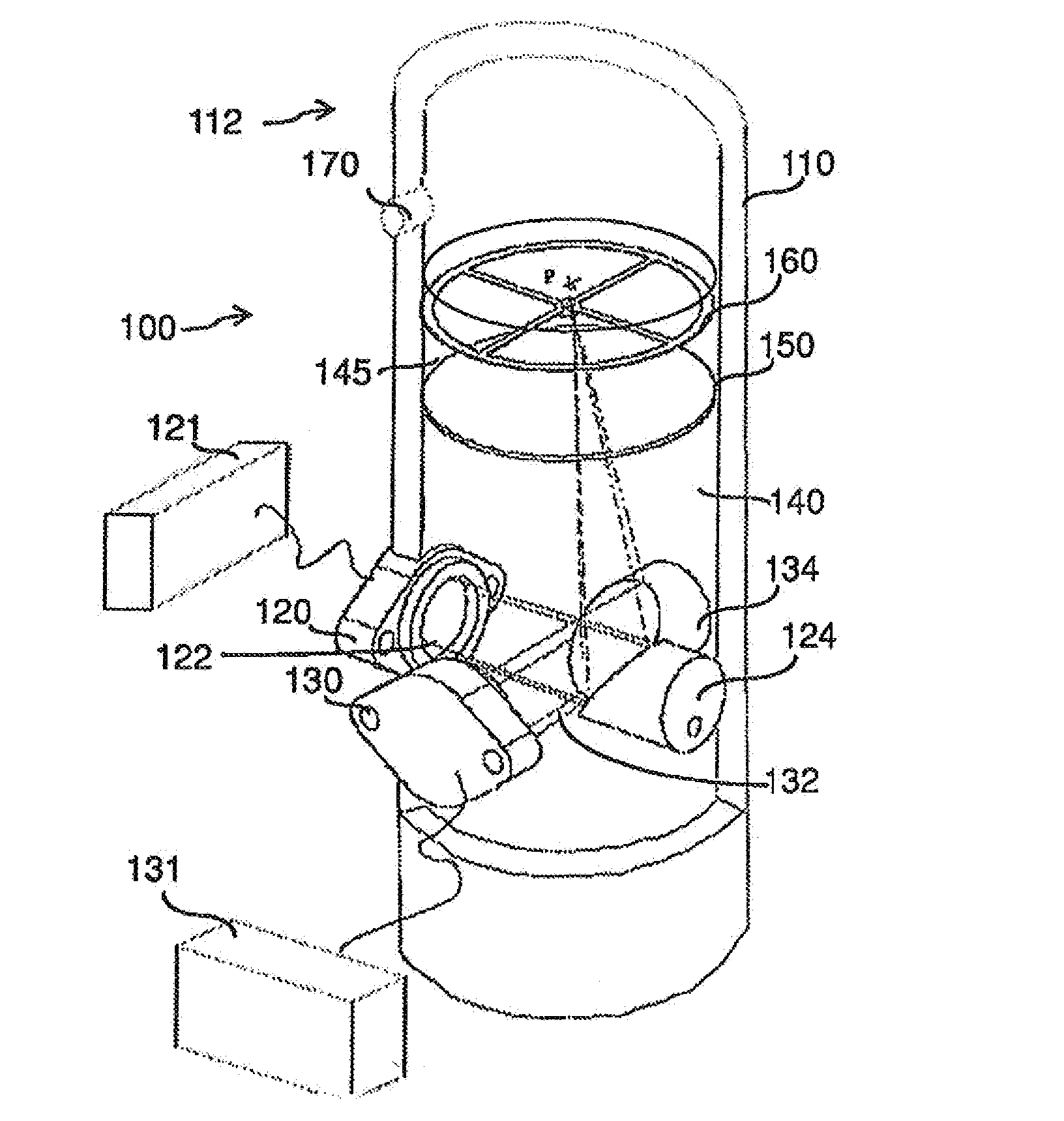
[0081]It is reminded that only weak cavitation is discussed within the scope of this invention. FIG. 1 shows a device 100 for nebulizing a liquid, comprising a tank 110 open at the top 112 and configured to contain the liquid to be nebulized. The device further comprises two ultrasonic-wave generators 120, 130 for transmitting two ultrasonic-wave fronts 122 and 132 respectively in the liquid, two means 124 and 134 respectively for focusing ultrasonic waves, each cooperating with said generator 120, 130 respectively, in order to concentrate ultrasonic waves at the same concurrent point P near the surface.

[0082]“Near” is to be understood as less than ten millimeters from the free surface of the liquid, and preferably less than five millimeters, and yet more preferably, less than three millimeters.

[0083]The flow chart shown in FIG. 2 represents a specific embodiment of the implementation method of the invention, which comprises:

[0084]a step 200 of generating at least two ultrasonic-wav...


PUM


Abstract

The invention relates to a device (100) for nebulizing a liquid, comprising: a vessel (110) that is open at the top portion thereof and configured so as to contain the liquid to be nebulized; at least two ultrasonic-wave generators (120, 130) for emitting at least two ultrasonic-wave fronts (122, 132) into the liquid; and at least two means (134, 124) for focusing the ultrasonic waves, each of which engages with one of said generators (120, 130) in order to concentrate ultrasonic waves at a single point P less than ten millimetres from the free surface of the liquid, wherein the vibration frequencies of the two wave fronts (122, 132) are different.

Description

FIELD OF THE INVENTION[0001]This invention concerns a device for nebulizing a liquid. It particularly applies to the nebulization of water.PRIOR ART[0002]The principle of acoustic nebulization is based on focusing an acoustic wave on the surface of a liquid. Several devices are used to achieve this phenomenon. The oldest is the acoustic fountain wherein the wave is oriented towards the free surface of a liquid at rest. If the acoustic intensity is sufficient, an acoustic fountain is formed, the conical shape of which focuses the ultrasonic wave. This fountain comes from the nonlinearity of acoustic propagation that transforms a small amount of vibratory energy into continuous energy (continuous flow) and forms a fountain which flows from the base upward. The acoustic wave propagates in this fountain and the acoustic concentration increases as the cross section of the fountain is reduced.[0003]When a sufficient concentration is reached, the wall of the fountain vibrates strongly, exc...

Claims


Application Information

Patent Timeline
Patent Type & Authority Applications(United States)
IPC IPC(8): B05B17/06
CPCB05B17/0615C02F1/36C02F1/12C02F2103/002C02F2103/005C02F2103/08F24F6/12Y02A20/144
Inventor CHING, GILRENGGLI, HENRIPALLANCA, CHARLES
Owner ADLYNX
Why Eureka
Try Eureka