
Integrated OCT-Refractometer System for Ocular Biometry

a biometric and oct-refractometer technology, applied in the field of integrated oct-refractometer systems, can solve the problems of non-negligible changes in the biometric of the patient's eye, increased difficulty in adjusting the oct-refractometer, so as to achieve better accuracy

Active Publication Date: 2015-03-19
ALCON INC
View PDF10 Cites 38 Cited by
  • Summary
  • Abstract
  • Description
  • Claims
  • Application Information

AI Technical Summary

Benefits of technology

The present instruments have limitations in accurately determining biometrical information due to the use of assumptions and averaged information. There is also a need for a system that can capture patient-to-patient variations and provide biometric information closer to the time of surgery. The technical effects of this patent text are improved accuracy and precision in determining biometrical information and improved surgical choices through a system that can capture patient-to-patient variations and provide biometric information closer to the time of surgery.

Problems solved by technology

1. One of the problems with the present instruments is that the methods that are used to determine biometrical information heavily rely on assumptions going into the used eye-models, such as the speed of ultrasound in the various ocular media and the refractive indices of various ocular media.
However, there can be non-negligible changes in the biometry of the patient's eye in the weeks leading up to the surgery.
4. Moreover, since the biometrical measurements are performed on a cataractous eye, the optical signals are often blurred or distorted to some degree.
5. Since in present procedures separate biometrical and imaging instruments are used, the biometrical and imaging data needs to be cross-referenced and registered, which raises additional challenges.
6. Beyond all the above problems of the preparatory biometry and imaging that can deliver sub-optimal results for a particular eye of a particular patient at a particular time, an additional problem is that biometry is not available during the surgery, even though it could provide useful additional feedback and control information for the surgeon.
In particular, presently no intra-operative microscope is available with a refractive biometric device and an OCT imaging system integrated into it.

Method used


Image

  • Integrated OCT-Refractometer System for Ocular Biometry
  • Integrated OCT-Refractometer System for Ocular Biometry
  • Integrated OCT-Refractometer System for Ocular Biometry

Examples


Embodiment Construction

[0026]In the following description specific details are set forth describing certain embodiments. It will be apparent, however, to one skilled in the art that the disclosed embodiments may be practiced without some or all of these specific details. The specific embodiments presented are meant to be illustrative, but not limiting. One skilled in the art may realize other material that, although not specifically described herein, is within the scope and spirit of this disclosure.

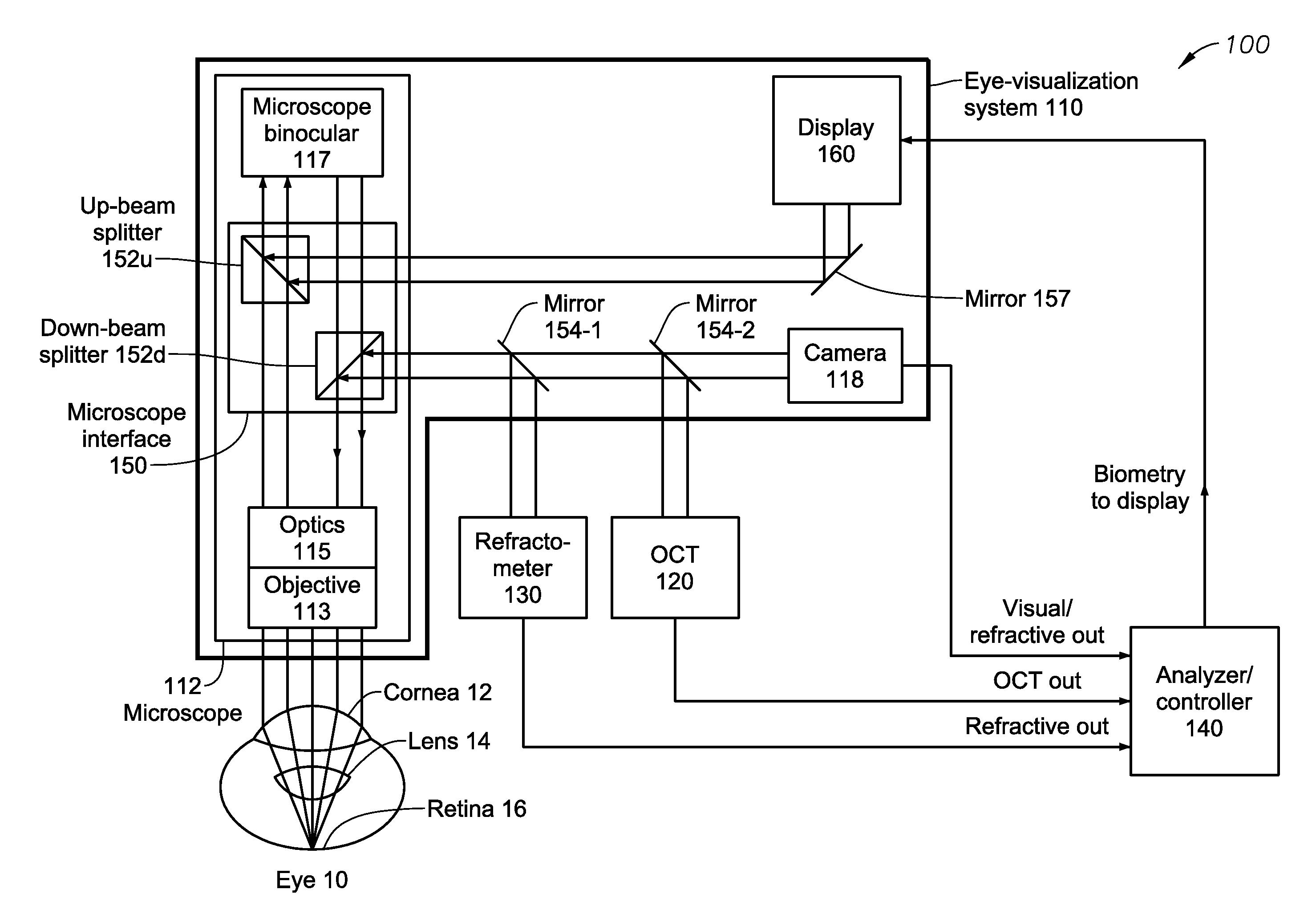
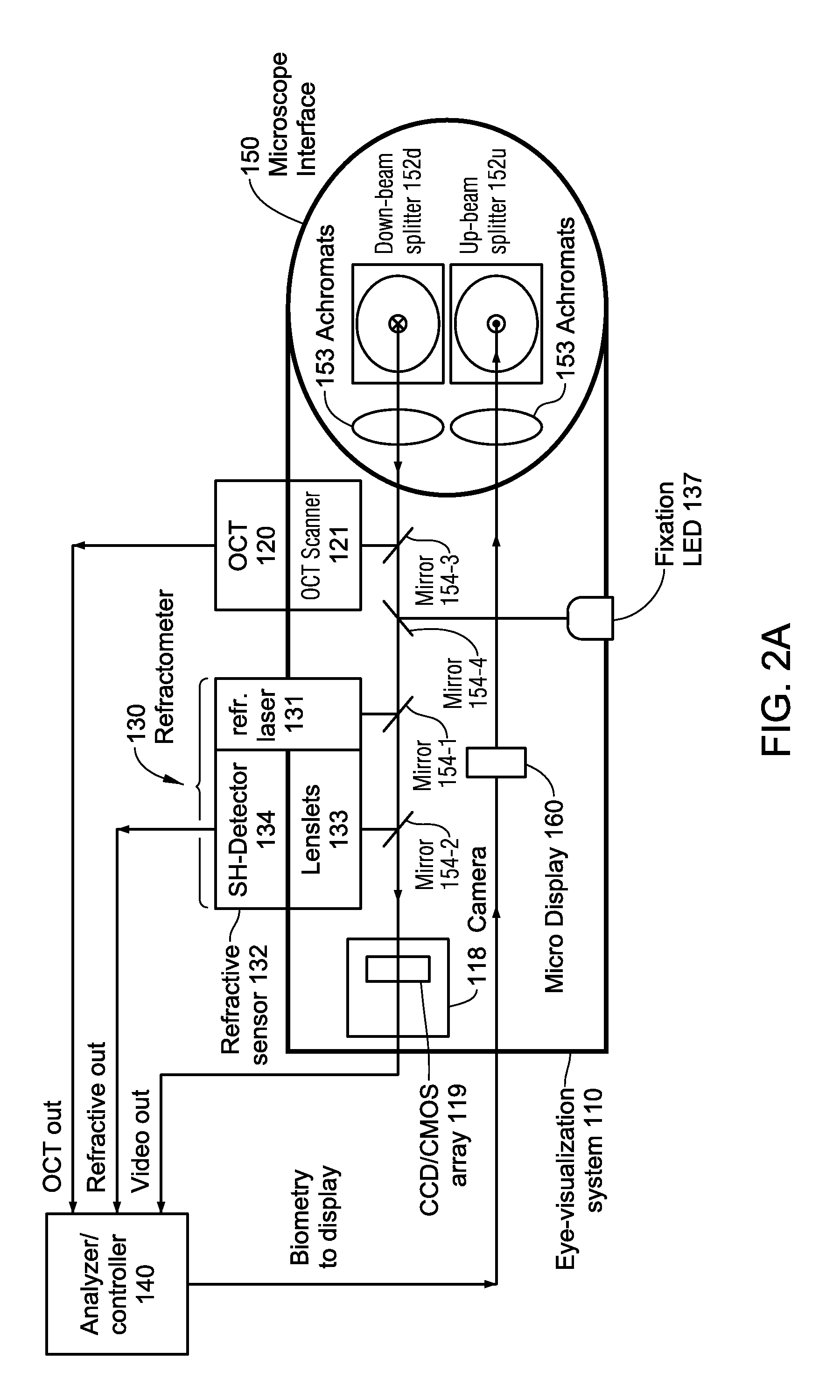
[0027]Embodiments of the present invention address the above outlined needs 1-8. In particular, instruments and methods according to the present invention include an Integrated-OCT-Refractometer System for ocular biometry that addresses those needs. Since this integrated system can be mounted on either a microscope or a slit lamp, it will be referred to as a Slit lamp-or-Microscope-Integrated-OCT-Refractometer System, or SMIORS. Slit-lamp-integrated systems can be useful for ophthalmic office-based systems whe...


PUM


Abstract

A Slit-lamp-or-Microscope-Integrated-OCT-Refractometer system includes an eye-visualization system, configured to provide a visual image of an imaged region in an eye; an Optical Coherence Tomographic (OCT) imaging system, configured to generate an OCT image of the imaged region; a refractometer, configured to generate a refractive mapping of the imaged region; and an analyzer, configured to determine refractive characteristics of the eye based on the OCT image and the refractive mapping, wherein the refractometer and the OCT imaging system are integrated into the eye visualization system.

Description

BACKGROUND[0001]1. Technical Field[0002]Embodiments disclosed herein are related to Integrated-OCT-Refractometer systems. In more detail, embodiments are related to eye-visualization systems, Optical Coherence Tomographic (OCT) imaging systems, and refractometers to determine refractive characteristics of the eye based on the OCT image and a refractive mapping.[0003]2. Related Art[0004]Current ophthalmic refractive surgical methods, such as cataract surgery, intra-corneal inlays, Laser-Assisted in situ Keratomileusis (LASIK), and photorefractive keratectomy (PRK), rely on ocular biometry data to prescribe the best refractive correction. Historically, ophthalmic surgical procedures used ultrasonic biometry instruments to image portions of the eye. In some cases these biometric instruments generated an A-scan of the eye: an acoustic echo signal from all interfaces along an imaging axis that was typically aligned with an optical axis of the eye: either parallel with it, or making only ...

Claims


Application Information

Patent Timeline
IPC IPC(8): A61B3/00A61B3/103A61B3/10
CPCA61B3/0025A61B3/103A61B3/102A61B3/0041A61B3/135A61F2009/00887A61F2009/00851A61F2240/002A61B3/18A61B3/1015
Inventor ARTSYUKHOVICH, ALEXANDER N.ASLAN, Z. ARASYU, LINGFENGBOUKHNY, MIKHAIL
Owner ALCON INC
Learn More