Light-scattering body, light-scattering body film, light-scattering body substrate, light-scattering body device, light-emitting device, display device, and illumination device

Active Publication Date: 2015-03-19
SHARP KK
View PDF5 Cites 65 Cited by
  • Summary
  • Abstract
  • Description
  • Claims
  • Application Information

AI Technical Summary

Benefits of technology

[0076]According to some aspects of the present invention, it is possible to provide a light-scattering body, a light-scattering body film, a light-scattering body substrate, a light-scattering body device, a light-emi

Problems solved by technology

50% or more of the outgoing light is absorbed by a polarizer arranged on an illumination light incident side of the liquid crystal display element, and efficiency of using the light from the light source is low.
However, acc

Method used


Image

  • Light-scattering body, light-scattering body film, light-scattering body substrate, light-scattering body device, light-emitting device, display device, and illumination device
  • Light-scattering body, light-scattering body film, light-scattering body substrate, light-scattering body device, light-emitting device, display device, and illumination device
  • Light-scattering body, light-scattering body film, light-scattering body substrate, light-scattering body device, light-emitting device, display device, and illumination device

Examples


third embodiment

(3) Third Embodiment

[0408]FIG. 15 is a schematic cross-sectional view showing an inorganic EL element substrate which configures a third embodiment of a display device according to the embodiment.

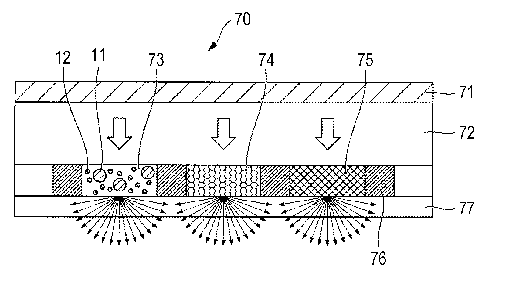
[0409]The display device according to the embodiment is substantially configured of a phosphor substrate configured of the substrate 77 including the light-scattering body film 73, the red phosphor film 74, the green phosphor film 75, the light absorption layer 76, the barrier 101, the wavelength selecting transflective film 111, the low-refractive-index film 121, and the like of the aforementioned light-emitting device according to the first to sixth embodiments formed thereon and an inorganic EL element substrate (light source) 250 which is attached to the phosphor substrate via the flattening film 72 and the like of the aforementioned light-emitting device according to the first to sixth embodiments.

[0410]The inorganic EL element substrate 250 is substantially configured of a substrate 2...

fourth embodiment

(4) Fourth Embodiment

[0433]FIG. 16 is a schematic cross-sectional view showing a fourth embodiment of a display device according to the embodiment. FIG. 17 is a schematic planar view showing the fourth embodiment of the display device according to the embodiment. In FIGS. 16 and 17, the same reference numerals will be given to the same constituent elements as those in the light-emitting device 70 shown in FIG. 7 and the organic EL element substrate 210 shown in FIG. 13, and descriptions thereof will be omitted.

[0434]A display device 260 according to the embodiment is substantially configured of a phosphor substrate 261 with the same configuration as that of the substrate 77, on which the light-scattering body film 73, the red phosphor film 74, the green phosphor film 75, the light absorption layer 76, the barrier 101, the wavelength selecting transflective film 111, the low-refractive-index film 121, and the like are formed, of the aforementioned light-emitting device according to t...

fifth embodiment

(5) Fifth Embodiment

[0459]FIG. 18 is a schematic cross-sectional view showing a fifth embodiment of a display device according to the embodiment. In FIG. 18, the same reference numerals are given to the same constituent elements as those in the light-emitting device 70 shown in FIG. 7 and those in the organic EL element substrate 210 shown in FIG. 13, and the description thereof will be omitted.

[0460]A display device 300 according to the embodiment is substantially configured of a phosphor substrate 301 with the same configuration as that of the substrate 77, on which the light-scattering body film 73, the red phosphor film 74, the green phosphor film 75, the light absorption layer 76, the barrier 101, the wavelength selecting transflective film 111, the low-refractive-index film 121, and the lie of the aforementioned light-emitting device according to the first to sixth embodiments are formed, an organic EL substrate (light source) 302, and a liquid crystal element 303.

[0461]The or...


PUM


Abstract

A light-scattering body includes at least light-transmitting resin, and first particles and second particles which are dispersed in the light-transmitting resin. An average grain size Da of the first particles is greater than an average grain size Db of the second particles. A refractive index na of the first particles is less than a refractive index nb of the second particles. The average grain size Db of the second particles is within a range of 150 nm≦Db≦300 nm.

Description

TECHNICAL FIELD[0001]The present invention relates to a light-scattering body capable of efficiently diffusing incident light and emitting the incident light to the outside, a light-scattering body film, a light-scattering body substrate, a light-scattering body device, a light-emitting device, a display device, and an illumination device.[0002]This application claims the benefit of priority of Japanese Patent Application No. 2012-092195 filed in Japan on Apr. 13, 2012, the entire contents of which are incorporated by reference herein.BACKGROUND ART[0003]In recent years, needs for flat panel displays (FPD) have increased with the development of highly-information oriented societies. Examples of the flat panel displays include a non-self-luminous liquid crystal display (LCD), a self-luminous plasma display (PDP), an inorganic electroluminescence (inorganic EL) display, and an organic electroluminescense (hereinafter, also referred to as an “organic EL” or an “organic LED”) display.[0...

Claims


Application Information

Patent Timeline
IPC IPC(8): F21V5/00F21V13/02G02B5/02F21V9/08F21V9/14
CPCF21V5/002F21V9/08F21V13/02G02B5/0242F21V9/14G02B5/0278H05B33/02H05B33/14H01L33/504H01L33/507H01L33/60H01L2933/0091H01L2924/0002H10K50/854H01L2924/00
Inventor BESSHO, HISANORIKODEN, MITSUHIROFUJITA, YOSHIMASA
Owner SHARP KK
Why Eureka
Try Eureka