Mutual Remediation of Effluents of Petroleum Production

Inactive Publication Date: 2010-07-15
PURESTREAM TECH +1
View PDF9 Cites 21 Cited by
  • Summary
  • Abstract
  • Description
  • Claims
  • Application Information

AI Technical Summary

Benefits of technology

[0008]Saline production water is often available in the same location as flares, burners, heaters, engines and compressor stations. Basic design concepts have been developed for using production water to effectively scrub the emissions of volatile organic compounds, unburned hydrocarbons, combustion particulates, and sulfurous oxides. From these combustion sources, systems in accordance with the invention simultaneously put the waste heat from these combustion sources to beneficial use to evaporate production brine, thus reducing the volume of saline production water to be disposed of, in an environmentally responsible manner.

Problems solved by technology

In many oil / gas fields, the quantities of waste heat available are not sufficient to process the amount of saline water produced in the same area.

Method used


Image

  • Mutual Remediation of Effluents of Petroleum Production
  • Mutual Remediation of Effluents of Petroleum Production
  • Mutual Remediation of Effluents of Petroleum Production

Examples


Embodiment Construction

[0019]It will be readily understood that the components of the present invention, as generally described and illustrated herein, could be arranged and designed in a wide variety of different configurations. Thus, the following more detailed description of the embodiments of the system and method of the present invention, as represented here and in the Appendix attached hereto, is not intended to limit the scope of the invention, as claimed, but is merely representative of various embodiments of the invention.

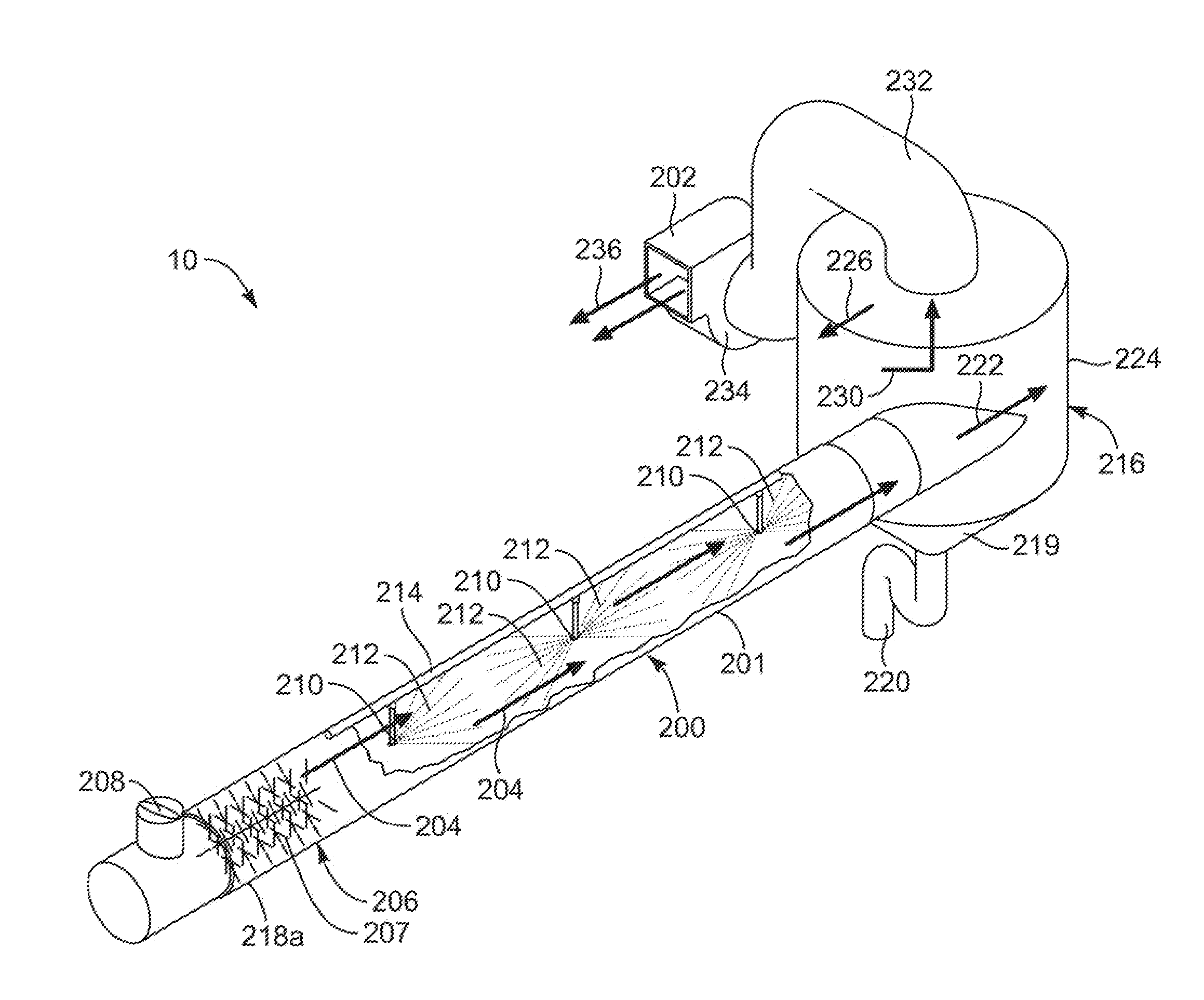
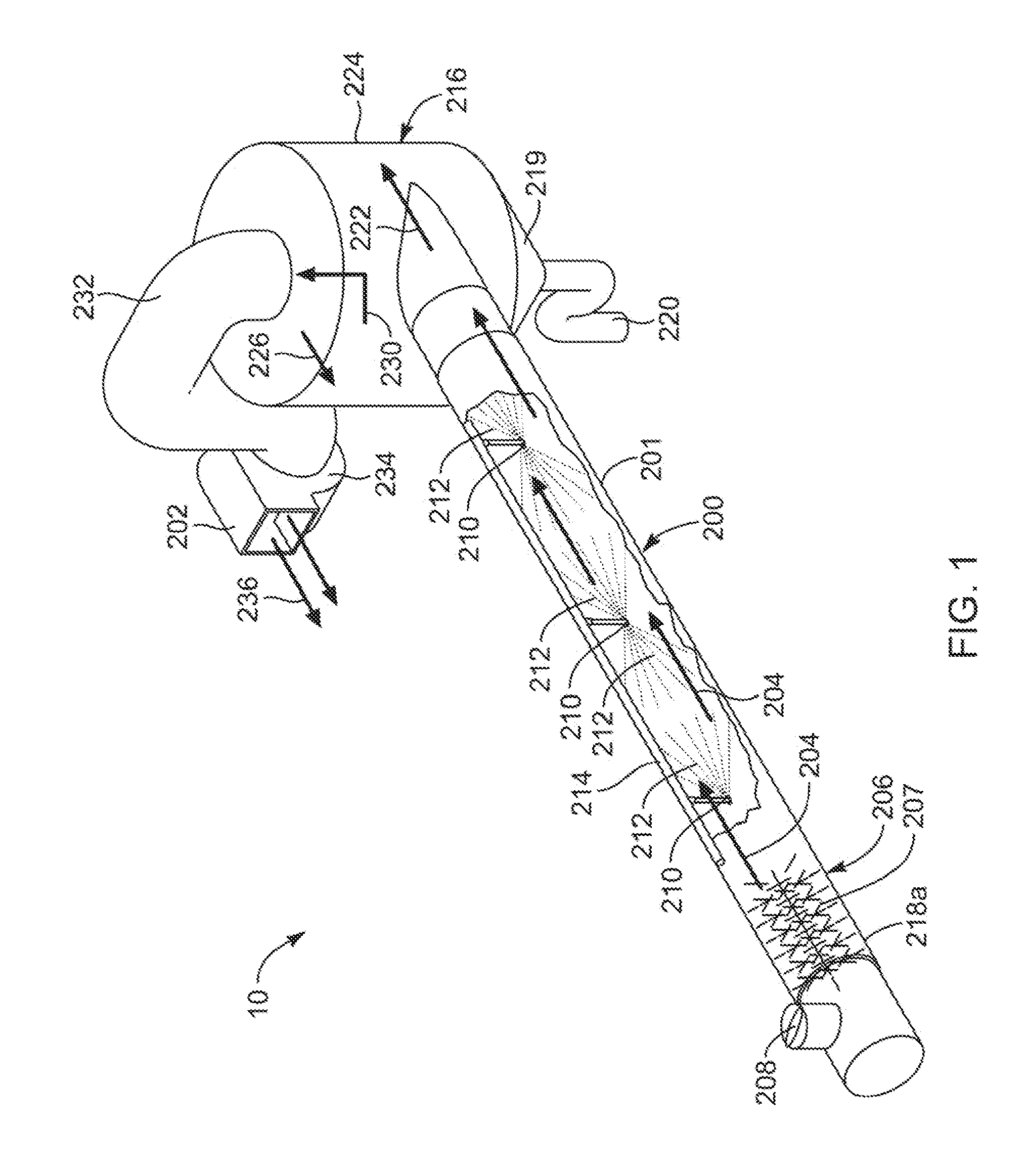
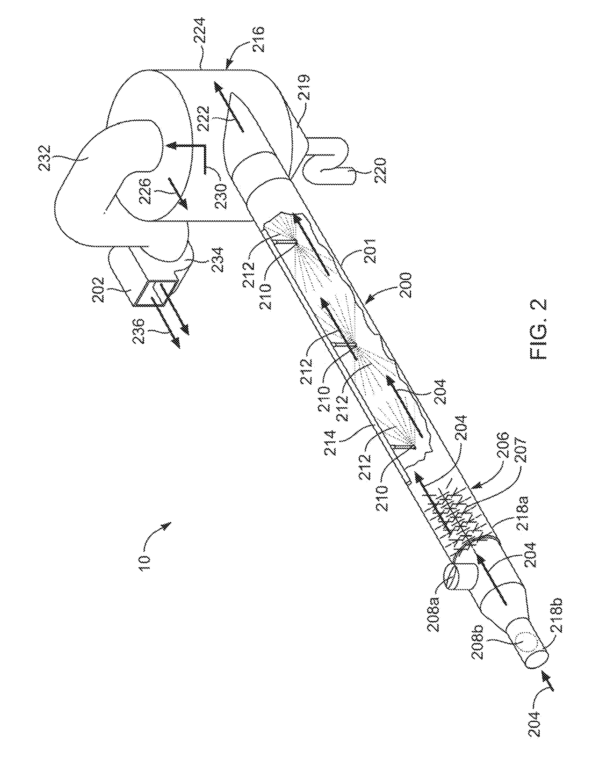
[0020]Notwithstanding consolidation of multiple wells at a single production site, as well as various waste containment and site restoration, environmental impacts continue from the production of natural gas and oil. Typically, sources of particulate emissions include heaters used to reduced the viscosity of oil. Likewise, various motors or engines designed to run on petroleum byproducts such as “field gas” produce heat and hydrocarbon emissions. Meanwhile, production of small q...


PUM

PropertyMeasurementUnit
Pressureaaaaaaaaaa
Areaaaaaaaaaaa
Energyaaaaaaaaaa

Abstract

Petroleous production is associated with effluents well known to foul lines, nozzles, and containers while consuming substantial energy to assist in both production and remediation. A heat exchanger and manifold system maximizes flows, minimizes changes in flow cross-section, and maximizes heat transfer area, while recycling both water and heat between processes. Dirty regions and clean regions result from scrubbing horizontal exhaust stacks and evaporation of production water in concert to remediate one another, while recycling a significant portion of the energy consumed by each. The heat exchanger relies on a manifold having many layered conduits, each connected to a single layer level of one or more cylindrical conduits in the exchanger. The cylinders of the exchanger themselves are arranged in multiple layers, each layer of a heat exchanger element being connected to a single layer of the manifold. Any shape of cylinder may work, but a right circular cylinder having corrugated sheets spacing the layers may be simple to construct.

Description

RELATED APPLICATIONS[0001]This application claims the benefit of co-pending U.S. Provisional Patent Application Ser. No. 61 / 144,665 filed Jan. 14, 2009 and U.S. Provisional Patent Application Ser. No. 61 / 144,694 filed Jan. 14, 2009, and incorporates by reference the entirety of each thereof.BACKGROUND[0002]1. The Field of the Invention[0003]This invention relates to oil and gas production and, more particularly, to novel systems and methods for environmental protection from, and remediation of, production materials and processes.[0004]2. The Background Art[0005]The production and transportation of petroleum resources, including oil and natural gas, often involves the introduction of emissions of substances considered pollutants into the natural environment. Often the production areas are in locations regarded as being particularly environmentally sensitive. Sources of pollutants include engines, heaters, flares, road surfaces, and production fluids themselves. Production water often...

Claims


Application Information

Patent Timeline
IPC IPC(8): B01D3/38F28D7/10F28F9/02
CPCB01D1/0058F28F1/105B01D1/16B01D1/20B01D1/30B01D5/0012B01D5/0039B01D5/006B01D47/06C02F1/12C02F2103/18C02F2103/365F23J15/022F23J2217/50F28D7/103F28D21/0003B01D1/14Y02W10/37
Inventor BATTY, J. CLAIRBELL, DAVID A.COX, CRAIG E.
Owner PURESTREAM TECH
Why Eureka
Try Eureka