Methods and Apparatus for Robotic Zipper

a robotic zipper and zipper technology, applied in the field of robotic zippers, can solve the problems of difficult manipulation of zippers placed at the back of a dress or the back of a boot, the inability to improve the basic rudimentary function of zippers for users,

Active Publication Date: 2015-03-26
MASSACHUSETTS INST OF TECH
View PDF1 Cites 50 Cited by
  • Summary
  • Abstract
  • Description
  • Claims
  • Application Information

AI Technical Summary

Benefits of technology

[0010]A related object of the invention is to provide the actuated zipper slider the means to determine the location and position of the zipper slider on the zipper tape and a means for a processor to electrically signal the motor to move in a forward or reverse direction. The actuated zipper would enable persons of limited dexterity and limited abilities to have a means to control the position of the actuated zipper on the body and would also be useful and comfortable in everyday life in the assistance of donning and doffing clothing.
[0011]Another object of the embodiment of the invention is to provide an actuated zipper slider with a motor and gear box that is also mechanically coupled with the zipper teeth. In one preferred embodiment the zipper slider can be attached to a traditional off-the-shelf market bought zipper. However, in yet another embodiment the zipper teeth can be mechanically enhanced to couple exactly with the gears of the actuated zipper and thereby increase the reliability of the coupling to the zipper teeth in order to prevent the slider from running off the zipper track. Additionally, the reliable coupling of the zipper teeth also increases the efficiency of the motor in providing the appropriate amount of torque forces that the actuated zipper can manage.
[0017]Further embodiments of the invention can assist in the usefulness of the invention for everyday use by incorporating a power source for the motor, visual light indicators on the chassis for visibility and wearer feedback as well as indicators that are sensitive to sound and the sense of touch or gesture.
[0024]Manifestations of the robotic zipper system are possible wherein the zipper slider geometry is retained by the zipper tape, such as with a traditional zipper. Also within the scope of the invention, the zipper slider geometry could be integrated into the chassis. For example, where the zipper halves have zipper teeth, the chassis can have a bottom plate with a channel forming the zipper slider geometry. In such embodiments, the channel can guide the zipper teeth into and out of the zipper slider geometry for joining or separating the zipper tape. The zipper slider geometry could have a central post, which could have a hollow conduit. The bottom plate can further provide physical support for mechanical engagement of the gear system and the zipper teeth. It is further contemplated that the motor and gear system can selectively switch a back-drivable transmission for manual operation.

Problems solved by technology

One can appreciate that in an electronic and digital age that the prior art seek to electrically connect a garment with an electronic device however they fail to improve on the basic rudimentary function of the zipper for the persons using them.
Zippers can be notoriously difficult to manipulate for persons with a limited dexterity in the fingers or a handicap.
For example, zippers placed at the back of a dress or the back of a boot can be difficult to use and can require assistance from other persons.
Similarly, some extreme applications where gas tight zippers are used such as in chemical and biological hazmat suit zippers can be extremely difficult to operate with the force required to open and close them.
Additionally, zippers used in large structures such as tents and long cables can be burdensome to reach and arduous to control.

Method used


Image

  • Methods and Apparatus for Robotic Zipper
  • Methods and Apparatus for Robotic Zipper
  • Methods and Apparatus for Robotic Zipper

Examples


Embodiment Construction

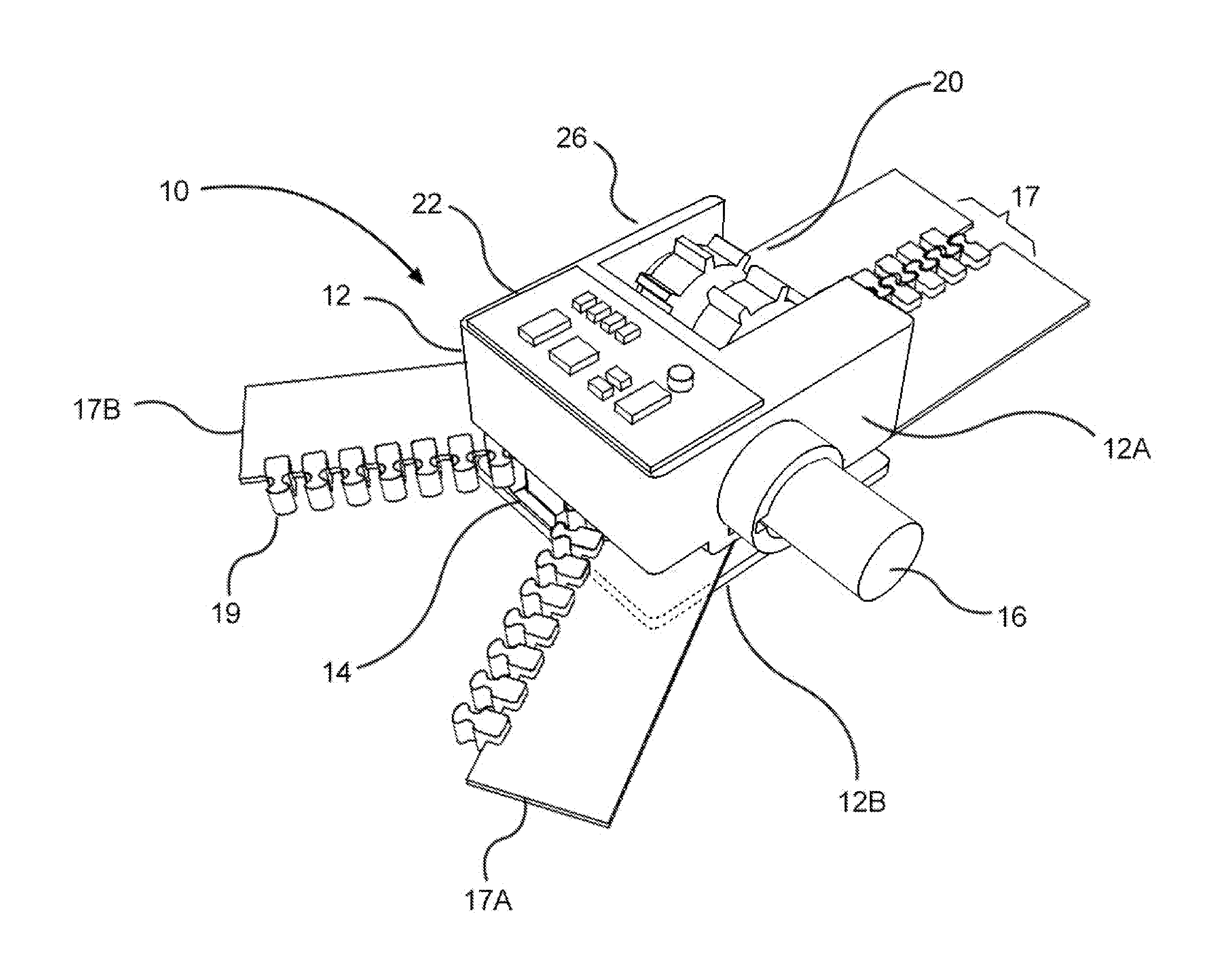
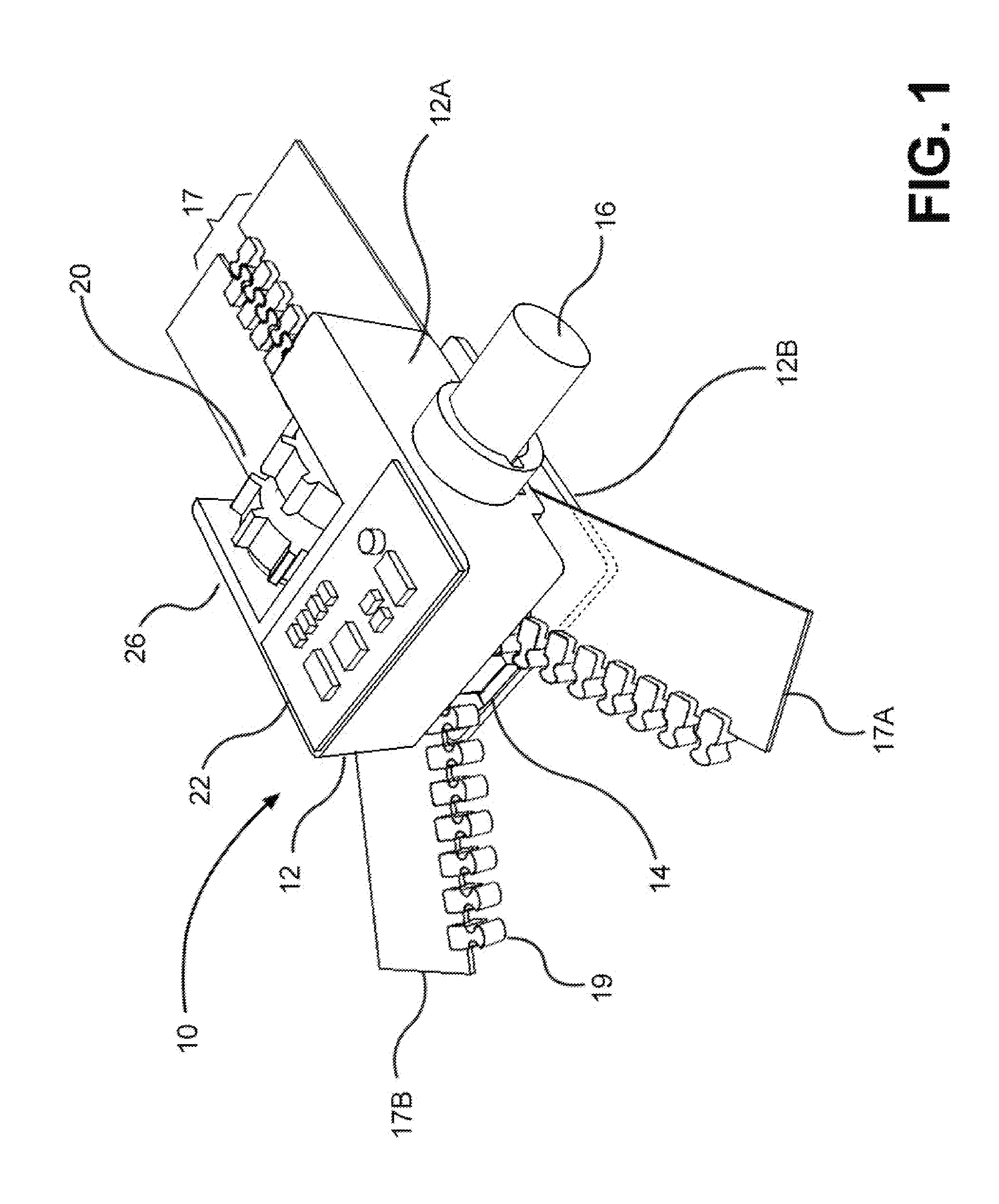
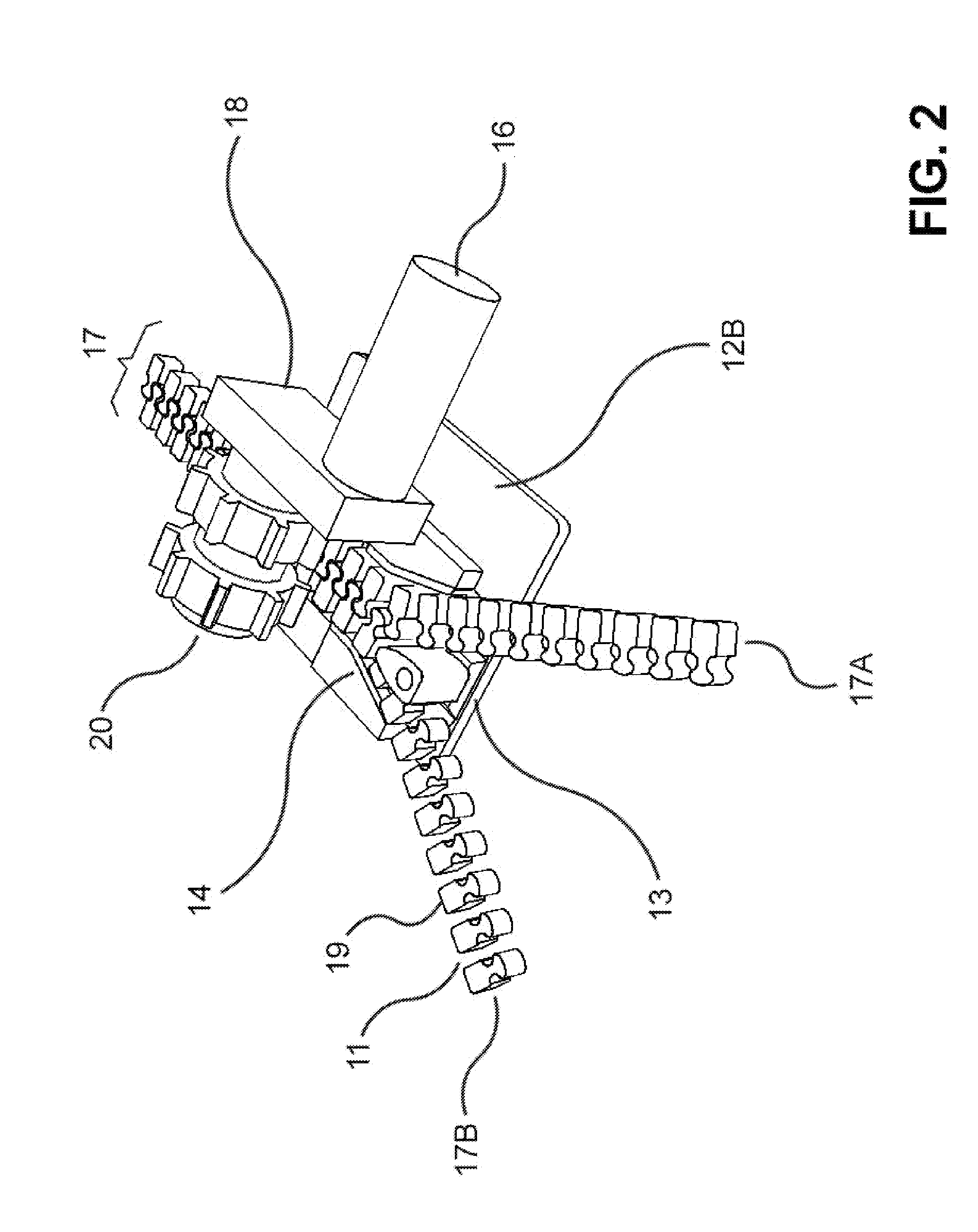
[0035]As is the case with many inventions, the present invention for a robotic zipper is subject to a wide variety of embodiments. However, to ensure that one skilled in the art will fully understand and, in appropriate cases, be able to practice the present invention, certain preferred embodiments of the broader invention revealed herein are described below and shown in the accompanying drawings.

[0036]Pursuant to the invention, a robotic zipper system can be embodied in relation to a zipper or a continuous closure for joining edges, such as but not limited to edges of fabric, that can be augmented with robotic attributes, such as sensing, actuation and computation, to create a programmable robotic zipper closure. With this in mind and looking more particularly to the accompanying figures, a first preferred embodiment of the present invention for a robotic zipper system is indicated generally at 10 in FIG. 1 and in an exploded view in FIG. 3. There, one sees that the robot zipper 10...


PUM


Abstract

A robotic zipper system for joining and separating zipper halves of a zipper tape. A chassis retains an actuator that drives a zipper slide geometry along the zipper tape to join or separate the zipper tape. A sensor can determine zipper slide position, and a control module can provide an electrical signal to the motor to move in forward or reverse. The actuator can have a motor that drives a gear system that mechanically engages zipper teeth. Teeth of the gear system can be out of phase to mesh with alternating gaps between the zipper teeth. The actuator can be removable relative to a zipper slide. Zipper slide geometry could be integrated into the chassis, such as in the form of a channel, potentially with a central post. A sensor could be positioned to detect the presence or absence of zipper teeth through an opening in a base plate.

Description

RELATED APPLICATION[0001]This application claims priority to U.S. Provisional Patent Application No. 61 / 880,926, filed Sep. 22, 2013, which is incorporated herein by reference.FIELD OF THE INVENTION[0002]The present invention relates generally to a robotic zipper for fabric joining, which may alternatively be referred to as an electric-mechanical machine guided by electronic circuitry and computer programming. Stated more particularly, disclosed herein is a continuous closure for fabric edge joining and augmented with robotic attributes including sensing, actuation and computation to create a programmable zipper closure.BACKGROUND OF THE INVENTION[0003]Gideon Sundback, an early designer of the modern zipper obtained a U.S. Pat. No. 1,219,881 for the ‘Separable Fastener’. In 1923 the name was rebranded as the “zipper” by the B.F. Goodrich Company which integrated the zipper into rubber boots and tobacco bags. In the 1930s the zipper was popularized in the fashion industry for closure...

Claims


Application Information

Patent Timeline
Patent Type & Authority Applications(United States)
IPC IPC(8): A44B19/30A44B19/28
CPCA44B19/303Y10S901/46A44B19/28A44B19/285A44B19/26Y10T24/2566
Inventor WHITON, ADAM
Owner MASSACHUSETTS INST OF TECH
Why Eureka
Try Eureka