Method for operating a snapping unit having stripper plates with variable spacing

a technology of stripper plate and variable spacing, which is applied in the field of snapping units, can solve the problems of grain loss, time delay in the adjustment of snapping-gap width, and relatively late detection of the diameter of the stand to be harvested

Inactive Publication Date: 2015-03-26
CLAAS SELBSTFAHRENDE ERNTEMASCHINEN GMBH
View PDF14 Cites 9 Cited by
  • Summary
  • Abstract
  • Description
  • Claims
  • Application Information

AI Technical Summary

Benefits of technology

[0012]In an embodiment, the snapping-gap is automatically varied. In general, an operator specifies a setting for the snapping-gap width before the harvesting process is started. The automatic variation implemented during the harvesting process therefore relieves an operator guiding the carrier vehicle of the task of adjusting the snapping-gap width during the harvesting process.
[0013]In particular, the number of crop stalks and the spacing therebetween is determined. The combination of counting and determining the spacing within a row of crop stalks makes it possible to inspect the quality of the sowing. In particular, it is possible to document the placement of two seed corns directly next to one another and to document the omission of the sowing of a single grain of seed corn within a row.

Problems solved by technology

A disadvantage of the method known from EP 2 412 228 A1 is that a change in diameter in the stand to be harvested is detected relatively late, since the change in diameter cannot be detected until the plant stalk is already located between the stripper plates.
This results in a time delay in the adjustment of the snapping-gap width.
As a result thereof, a snapping-gap width can be set to be too large due to a previous change in spacing between the stripper plates and thereby result in grain losses due to the lower end of the crop being drawn in by snapping rollers disposed underneath the stripper plates (so-called “butt shelling”).

Method used


Image

  • Method for operating a snapping unit having stripper plates with variable spacing
  • Method for operating a snapping unit having stripper plates with variable spacing
  • Method for operating a snapping unit having stripper plates with variable spacing

Examples


Embodiment Construction

[0028]The following is a detailed description of example embodiments of the invention depicted in the accompanying drawings. The example embodiments are presented in such detail as to clearly communicate the invention and are designed to make such embodiments obvious to a person of ordinary skill in the art. However, the amount of detail offered is not intended to limit the anticipated variations of embodiments; on the contrary, the intention is to cover all modifications, equivalents, and alternatives falling within the spirit and scope of the present invention, as defined by the appended claims.

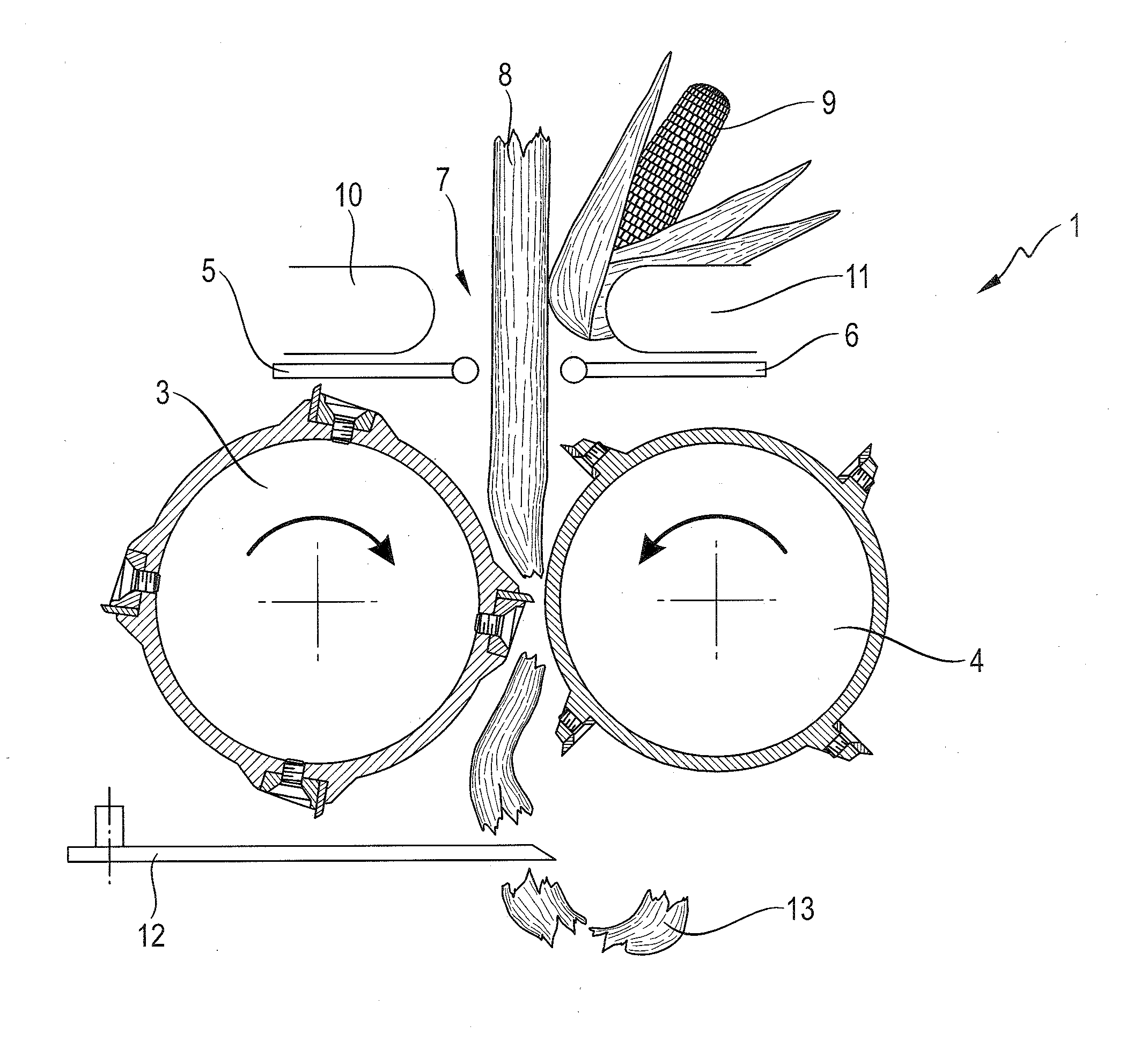
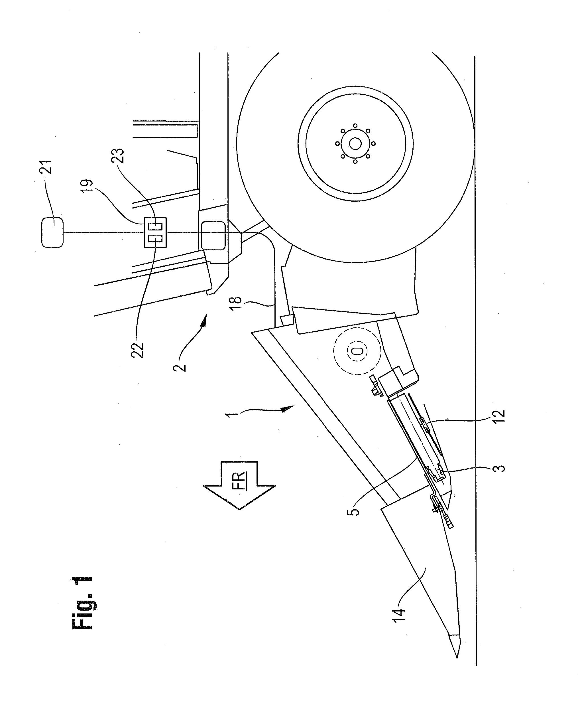
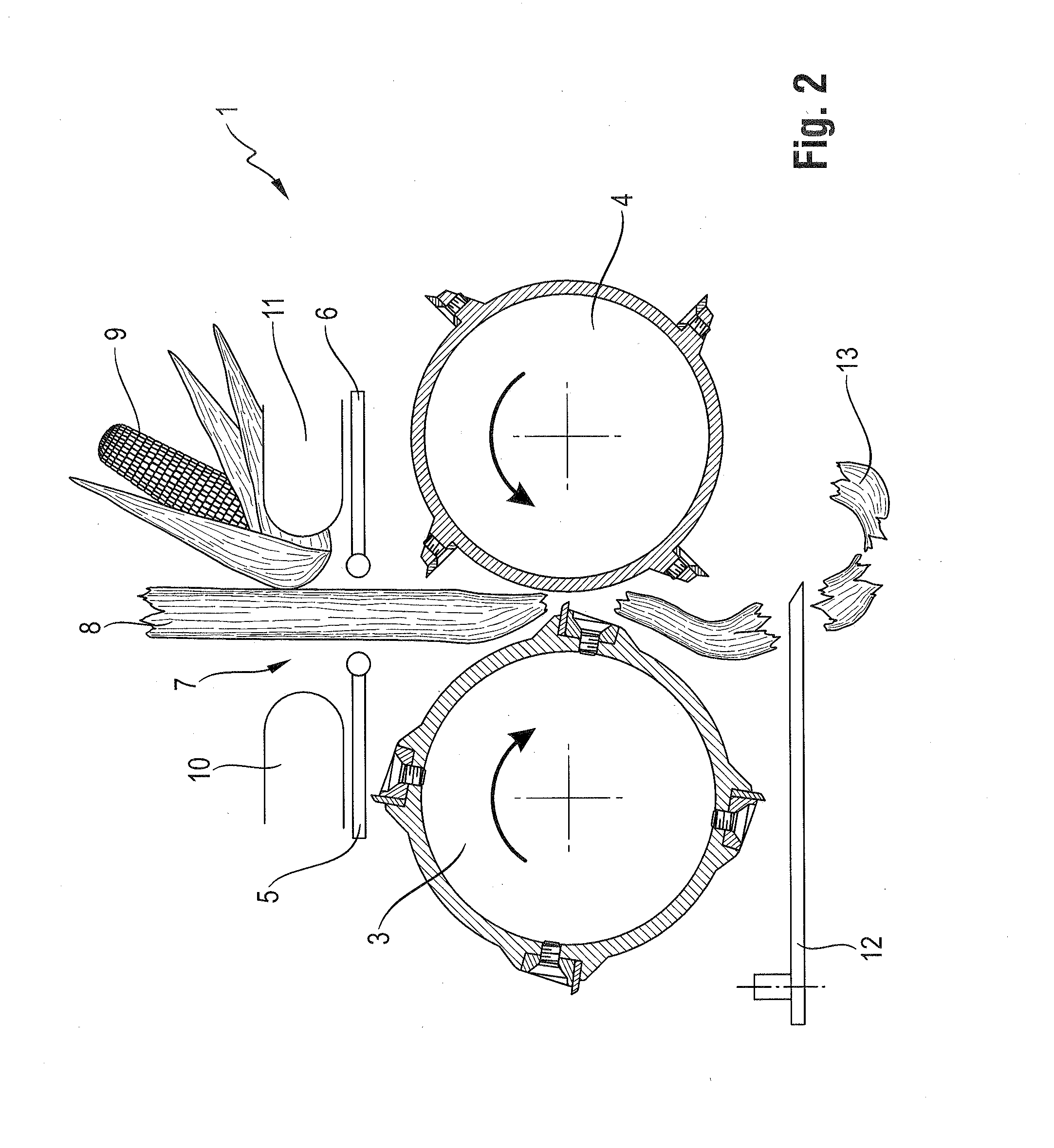
[0029]FIG. 1 shows a schematic depiction of a snapping device 1 for harvesting stalk crop that is mounted, in a rear region thereof, on a carrier vehicle 2 such as a combine harvester or a forage harvester. The snapping device 1, which operates in a row-dependent manner, simultaneously grasps a plurality of rows of stalk crop. A control unit 19 is disposed on the carrier vehicle 2, which is...


PUM


Abstract

A method for operating a snapping device to harvest stalk crop relies upon stripper plates disposed in pairs and having a variable spacing therebetween. A snapping gap is formed by or in the variable spacing. Plant stalks are drawn into the snapping gap to sever crop fruit from crop stalks by the stripper plates. The diameter of the crop stalks is determined before entry into the snapping gap by a sensor device disposed in front of the snapping gap. A width of the snapping gap is adjusted depending on the diameter value that is determined.

Description

CROSS-REFERENCE TO A RELATED APPLICATION[0001]The invention described and claimed hereinbelow is also described in German Patent Application DE 10 2013 110498.3, filed on Sep. 23, 2013. The German Patent Application, the subject matters of which is incorporated herein by reference, provides the basis for a claim of priority of invention under 35 U.S.C. 119(a)-(d).BACKGROUND OF THE INVENTION[0002]The present invention relates to a snapping unit for use in an agricultural working machine.[0003]Document EP 2 412 228 A1 makes known a method for operating a snapping unit. The snapping unit according to EP 2 412 228 A1 comprises stripper plates having spacing which can be varied by actuators and between which a snapping gap forms. The width of the snapping gap, i.e., the horizontal distance between the mutually opposed stripper plates, is predefined. The predefined snapping-gap width between the stripper plates is changed by moving the stripper plates away from one another or toward one a...

Claims


Application Information

Patent Timeline
Patent Type & Authority Applications(United States)
IPC IPC(8): A01D45/02
CPCA01D45/021
Inventor ZENTNER, SETH
Owner CLAAS SELBSTFAHRENDE ERNTEMASCHINEN GMBH
Why Eureka
Try Eureka