Pluggable Control Module For LED Lighting Device

a technology of led lighting and control module, which is applied in the field of luminaires, can solve the problems of affecting the validity of the original design principle of linear fixtures, and affecting the use of standard g13 based socket interfa

Inactive Publication Date: 2015-03-26
LIGHTEL TECH
View PDF1 Cites 24 Cited by
  • Summary
  • Abstract
  • Description
  • Claims
  • Application Information

AI Technical Summary

Benefits of technology

[0029]The control unit of the present invention supports a plug-and-play interface that allows the replacement and upgrade of the control unit to be safely performed without any tools by any end user, thus eliminating the need for an electrician.
[0030]Additionally, a new plug-and-play control module could add new functionality to the LED luminaire. For example, the old control module may not have dimming capability. By replacing the old control module with a new control module with dimming capability, the LED luminaire would become dimmable without any modification to the rest of the LED luminaire. Similarly, a new plug-and-play control module with an ambient light sensor would allow for automatic light adjustment of the LED lighting device without any modification to the rest of the LED luminaire.
[0031]Separately, a new plug-and-play control module may be used to upgrade existing functionality. For example, an older control module with a motion sensor that only has a detection range of 2 meters could be upgraded to a new control module with a better motion sensor that increases the detection range to 10 meters. In the same way, an older control module that uses an infra-red remote control that is limited to distances of up to 5 meters and cannot penetrate through a solid object may be replaced with a new control module using WiFi remote control that is effective over distances of up to 20 meters and can penetrate solid objects. Another example would be to use a new control module with a high-performance driver to achieve higher energy efficiency. An end user would be able to enjoy these upgrade functionalities without making any modification to the rest of the LED luminaire.
[0032]Different plug-and-play control modules would also allow for product differentiation. For examples, an IR-based plug-and-play control module would be available for users or areas that require IR remote control, while a WiFi-based plug-and-play control module would be available for users or areas that require WiFi-based remote control. In both cases, the rest of the LED luminaire would be kept exactly the same, reducing production and inventory costs while offering end users more choices and an LED luminaire with increased functionality.

Problems solved by technology

The relatively recent appearance of the LED tube on the market as a replacement for the fluorescent tube has challenged the validity of the original design principal for linear fixtures.
As such, there is no longer the need for easy and frequent tube replacement, and thus the use of the standard G13 based socket interface becomes meaningless.
At the same time, while an LED chip has a potential lifetime of over 100,000 hours, the average lifetime of an LED driver is around 20,000 to 30,000 hours, which limits the overall lifetime of the LED lamp.
The same lifetime limitation exists in the electronic components used in the LED light control module.
This limitation gives rise to a new problem unique to the LED luminaire; namely, the LED light source or lamp has a significantly longer lifetime than the driver and the control module.
Presently, all of the linear fixtures on the market hide the driver, the ballast, or the control module inside the fixture, making them difficult to access.
The traditional linear fixture design is clearly outdated with respect to the LED light source and driver.

Method used


Image

  • Pluggable Control Module For LED Lighting Device
  • Pluggable Control Module For LED Lighting Device
  • Pluggable Control Module For LED Lighting Device

Examples


example implementations

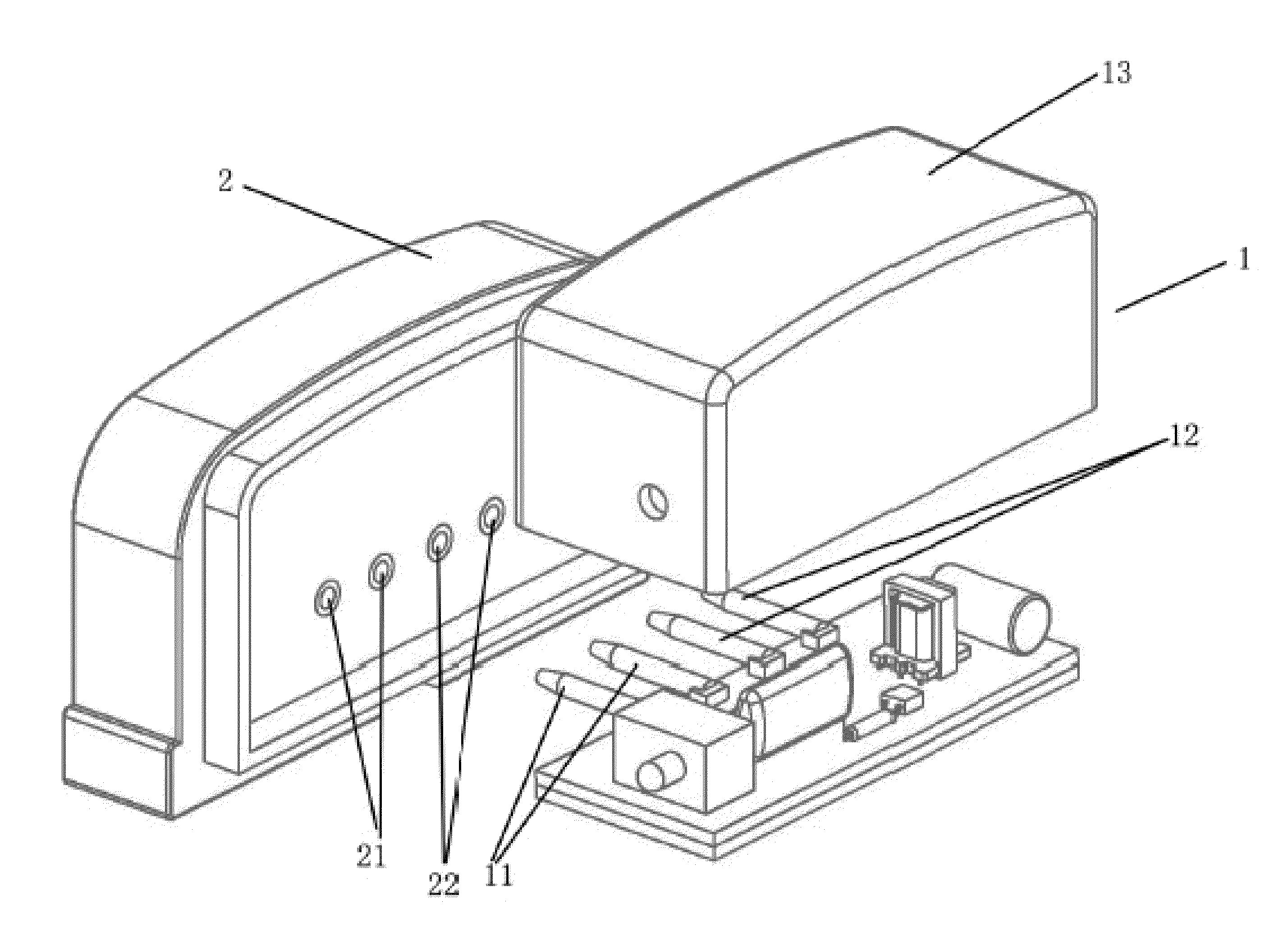
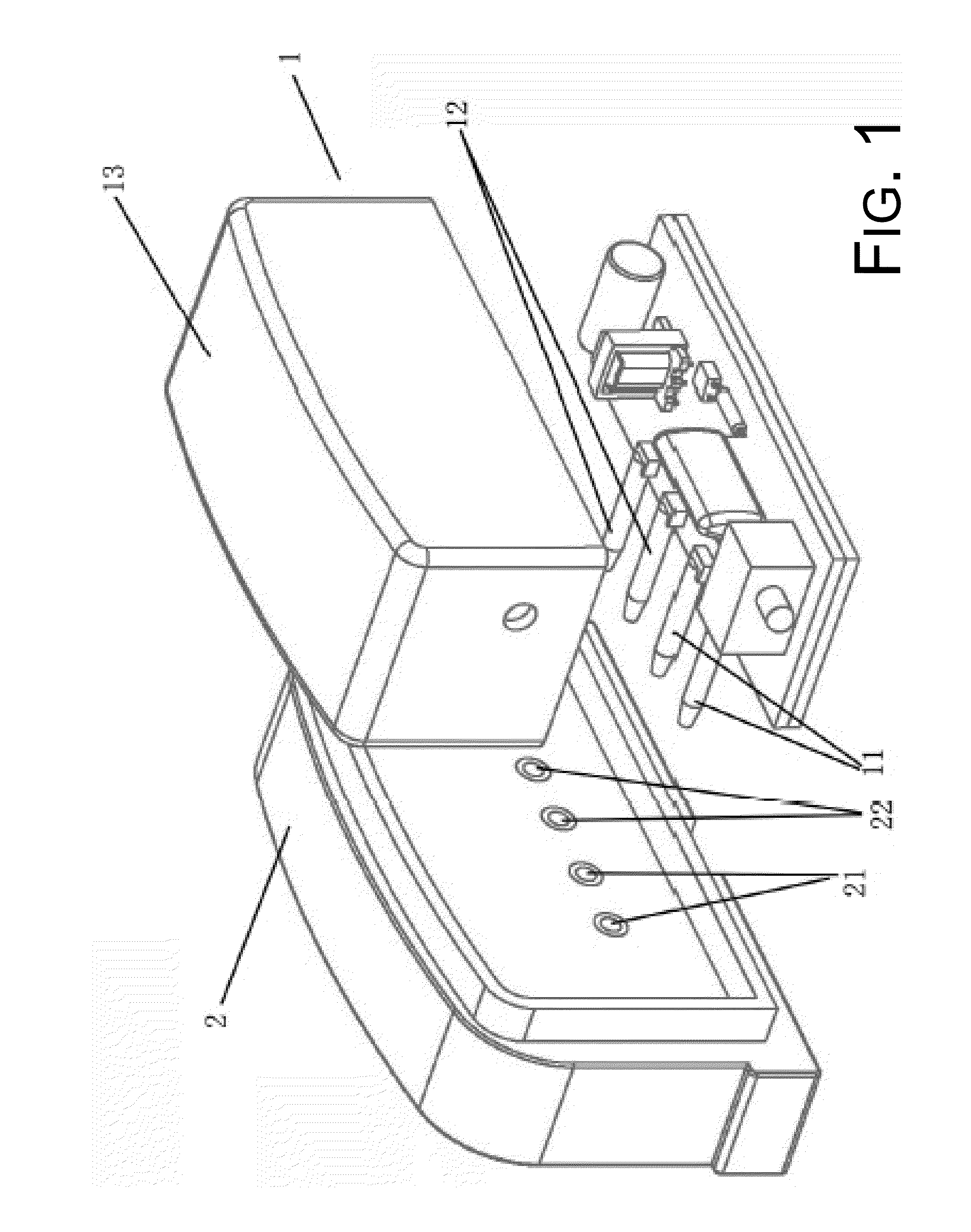
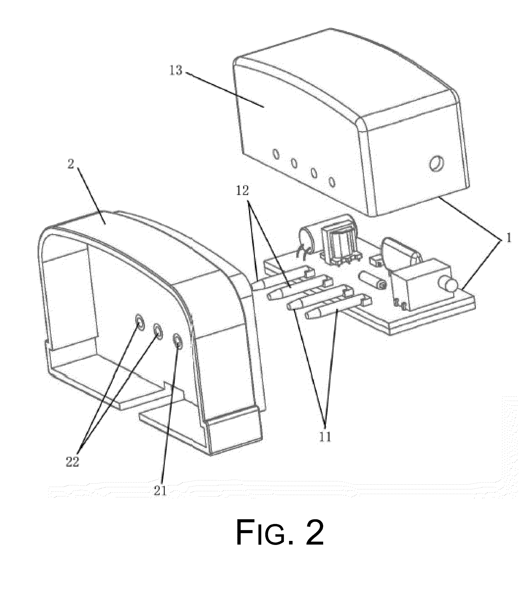
[0033]FIGS. 1 and 2 illustrates one non-limiting embodiment of the plug-and-play control module of the present invention. The plug-and-play control module comprises a main body 1 and a control module socket 2, wherein the control module socket 2 includes AC sockets 21 and DC sockets 22, with all sockets aligned in one row; the main body 1 includes a housing 13 made of insulating material, a driver for supplying the DC power, a control unit, an input port 11 and output port 12 consisting of cylindrical pins aligned in a row to match the sockets; the driver and the control unit reside inside the housing 13; part of the input port 11 and part of the output port 12 reside outside of the housing 13 and connect to the control module socket 2; the AC socket 21 connects to the input port 11 to receive external electricity; the control unit and the driver transmit the electricity via the output port 12 to the DC socket 22; the control unit includes the control signal receiver that receives e...


PUM


Abstract

Embodiments of a plug-and-play control module for a LED lighting device are described. In one aspect, a plug-and-play control module for a LED lighting device includes a main body and a control module socket. The control module socket includes an AC socket and a DC socket. The main body includes a housing, a control unit, an input port and an output port. The control unit resides inside the housing. A portion of the input port and a portion of the output port protrude outside the housing and connect to the control module socket. The control unit controls an output current flowing through the output socket and thus the on / off of the LED lighting device.

Description

CROSS REFERENCE TO RELATED PATENT APPLICATION[0001]The present disclosure claims the priority benefit of Patent Application No. 201310440236.2 filed on Sep. 25, 2013 with the State Intellectual Property Office of China.BACKGROUND[0002]1. Technical Field[0003]The present disclosure relates to the field of luminaires and, more particularly, to a pluggable control module for light-emitting diode (LED) lighting device.[0004]2. Description of the Related Art[0005]The lifetime of a traditional fluorescent tube is around 5000 hours and the ballast used to energize the tube has a lifetime of around 20,000 to 30,000 hours, as compared the lifetime of a lighting fixture which is over 100,000 hours. Due to the limitation posed by the shorter lifetime of fluorescent tubes, the design goal of linear lighting fixtures has been to use a standardized connection interface, such as the G13 socket, that facilitates the installation and uninstallation of the fluorescent tube into and out of the fixture...

Claims


Application Information

Patent Timeline
Patent Type & Authority Applications(United States)
IPC IPC(8): F21V23/06F21V23/04F21V23/00
CPCF21V23/06F21V23/006F21V23/0464F21V23/0471F21V23/0442F21V23/0435F21V15/015F21Y2115/10
Inventor LIU, WEIMAA, CHIA-YIUSHEN, PAI-SHENG
Owner LIGHTEL TECH
Why Eureka
Try Eureka