
Stacked circuit board assembly with compliant middle member

a technology of electronic circuit boards and middle members, which is applied in the direction of dielectric characteristics, printed circuit stress/warp reduction, electric apparatus casings/cabinets/drawers, etc., can solve the problems of metal clad circuit boards that are limited in design options, circuitry placed on metal clad baords must be relatively simple, and are exposed to significant amounts of shock, vibration, moisture and other contamination. , to achieve the effect of reducing the shearing of connecting

Active Publication Date: 2015-03-26
TRUMPET HLDG
View PDF7 Cites 6 Cited by
  • Summary
  • Abstract
  • Description
  • Claims
  • Application Information

AI Technical Summary

Benefits of technology

The present invention is related to reducing damage to electronic components caused by changes in the material they are surrounded by when exposed to heat. This is accomplished by introducing a middle layer that is compliant and will compress during the expansion of the material used to encapsulate the components. This reduces the shearing forces that can damage the components and pins that connect them. In summary, the invention is about making electronic components safer and more reliable in their packaging.

Problems solved by technology

However, metal clad circuit boards are limited in regards to design options, such as the fact that you can not put circuit vias through the metal layer as you can with a circuit board made of dielectric material.
Because of the limitations it is typical that high power circuits built on metal clad circuit boards are built using single layer (or single sided) boards.
Due to metal clad boards typically being confined to a single circuit board side it becomes difficult to make connections to all required points on a circuit, as such, the circuitry placed on the metal clad baord must be relatively simple.
Furthermore, because voltage regulators are used on engine powered sports equipment, they are exposed to significant amounts of shock, vibration, moisture and other contamination.
However, when the space between the two circuit boards is filled with the encapsulation compound and the assembly gets hot due to ambient or self generated heat, the expanding encapsulant can generate destructive forces attempting to push the circuit boards away from each other.
These forces put tensile stress on the pins, and shear and tensile stress on the solder joints which can cause the pin solder joints to be broken.

Method used


Image

  • Stacked circuit board assembly with compliant middle member
  • Stacked circuit board assembly with compliant middle member
  • Stacked circuit board assembly with compliant middle member

Examples


Embodiment Construction

[0033]Although the disclosure hereof is detailed and exact to enable those skilled in the art to practice the invention, the physical embodiments herein disclosed merely exemplify the invention which may be embodied in other specific structures. While the preferred embodiment has been described, the details may be changed without departing from the invention, which is defined by the claims.

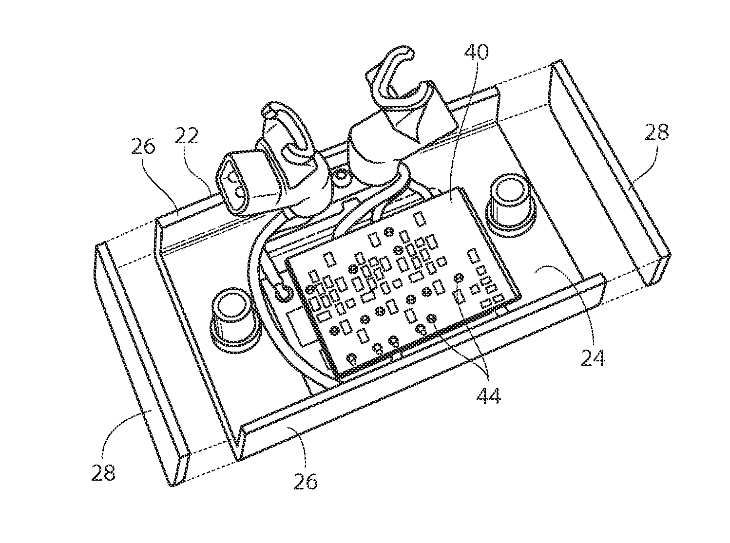
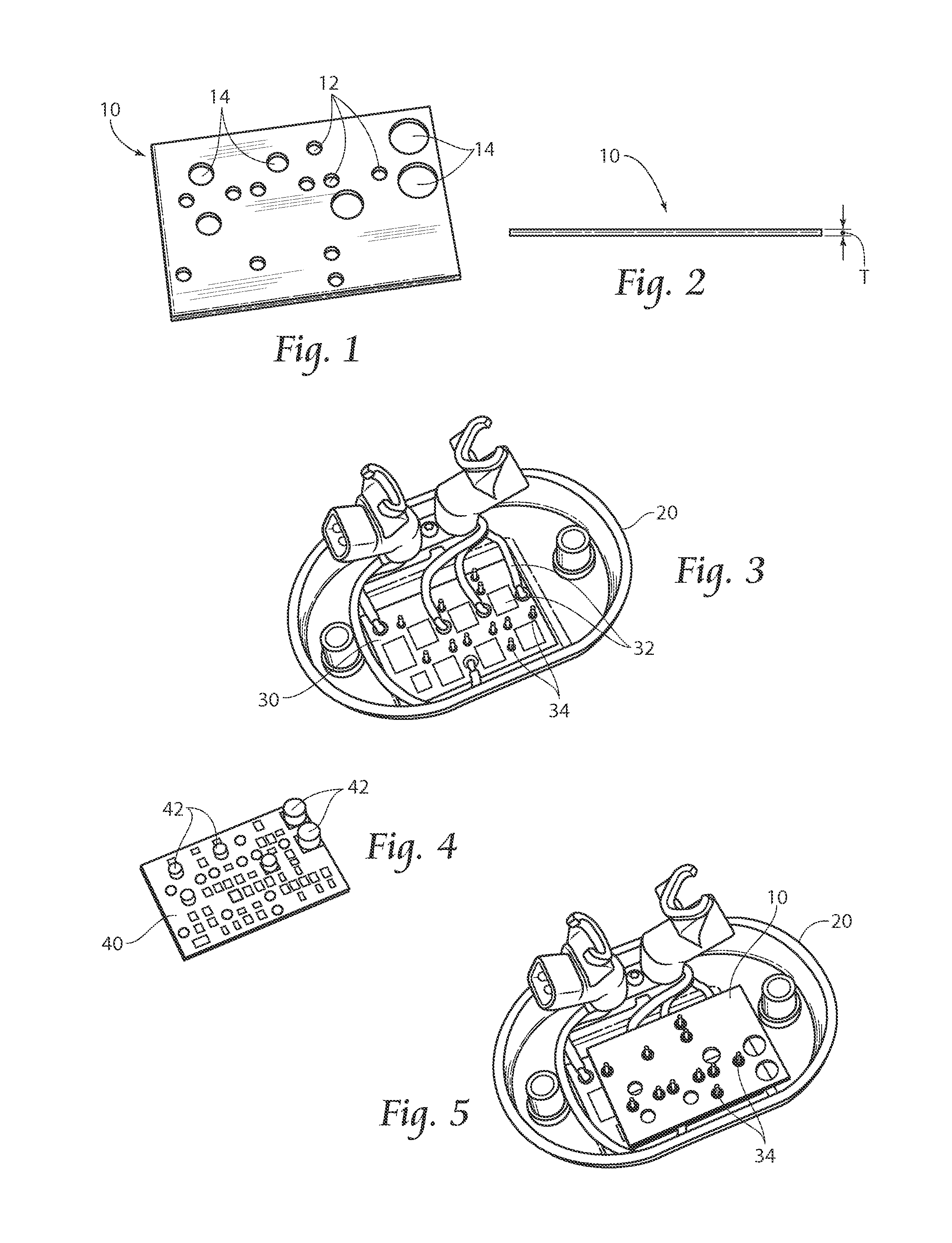
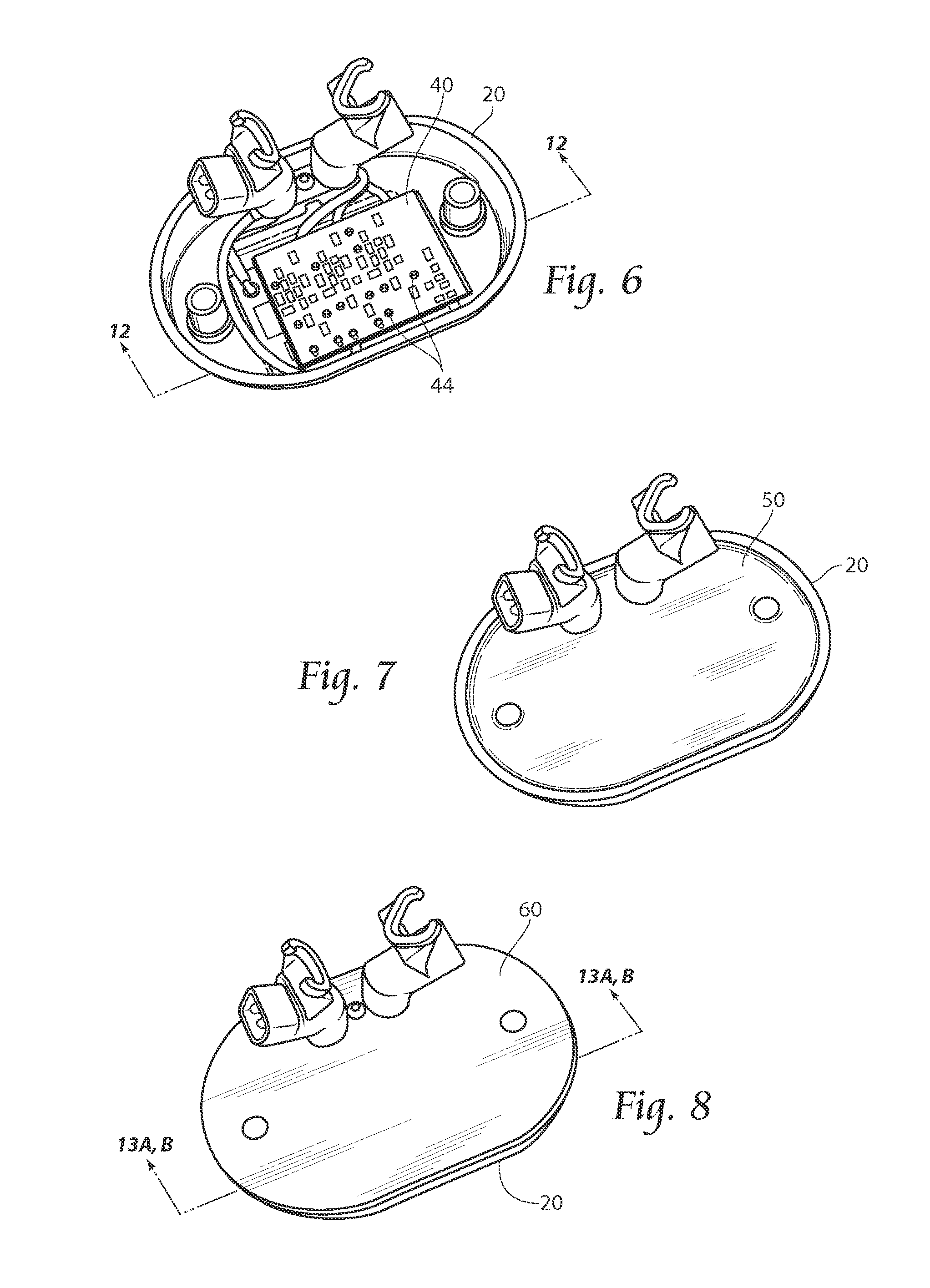
[0034]FIGS. 1 and 2 illustrate a compliant member 10 according to the present invention. As shown here, the compliant member 10 is of a closed-cell foam design and comprises Urethane foam; however, it could also be made from other materials such as closed-cell silicone rubber or other foamed elastomers, as non-limiting examples. Alternatively, in addition to being a pure closed-cell foam sheet design, the compliant member 10 may also comprise a closed-cell foam applied to an insulation film such as MYLAR®, thereby providing both the compliance for expansion and also adding a dielectric film with g...


PUM


Abstract

A compliant middle member to be used between encapsulated stacked circuit boards contained in an enclosure. The compliant middle member absorbing expansion forces from an encapsulant experiencing thermal expansion, thereby diverting and reducing the expansion forces exerted upon the electrical components.

Description

BACKGROUND OF THE INVENTION[0001]Embodiments of the present invention relate generally to stacked electronic circuit boards and more specifically to improved encapsulated stacked electronic circuit boards.[0002]It is known generally that heat is the enemy of electronic functionality, and that it is advantageous to conduct heat away from electronic components as effectively as possible. Heat may be induced by ambient conditions or from the electrical circuit boards themselves. One way to remove heat is to mount high heat producing components, like semiconductors, to metal clad (or metal backed) circuit boards and then mount the unpopulated surface of the metal clad circuit boards to a suitable heat sink or heat conduction medium such as a die cast or extruded aluminum housing. Any heat generated is transferred though the metal which provides a greater surface area to disperse the heat more rapidly in addition to reducing localized hot spots. However, metal clad circuit boards are lim...

Claims


Application Information

Patent Timeline
IPC IPC(8): H05K1/02
CPCH05K1/0271H05K1/144H05K2201/0133H05K2201/2036H05K2203/1322
Inventor LIBERTY, JAMESRAMONAS, JOHN W.MALLER, DENNIS A.
Owner TRUMPET HLDG
Learn More