
Room sterilization method and system

a sterilization method and a technology for rooms, applied in the field of disinfection, can solve the problems of c. diff /i>infection (cdi) that sickens and kills humans, current cleaning methods, such as chemical disinfection, and cannot be used as stand-alone practices, and achieve the effect of a faster processing time and a safer environmen

Active Publication Date: 2015-03-26
STERILIZ
View PDF13 Cites 96 Cited by
  • Summary
  • Abstract
  • Description
  • Claims
  • Application Information

AI Technical Summary

Benefits of technology

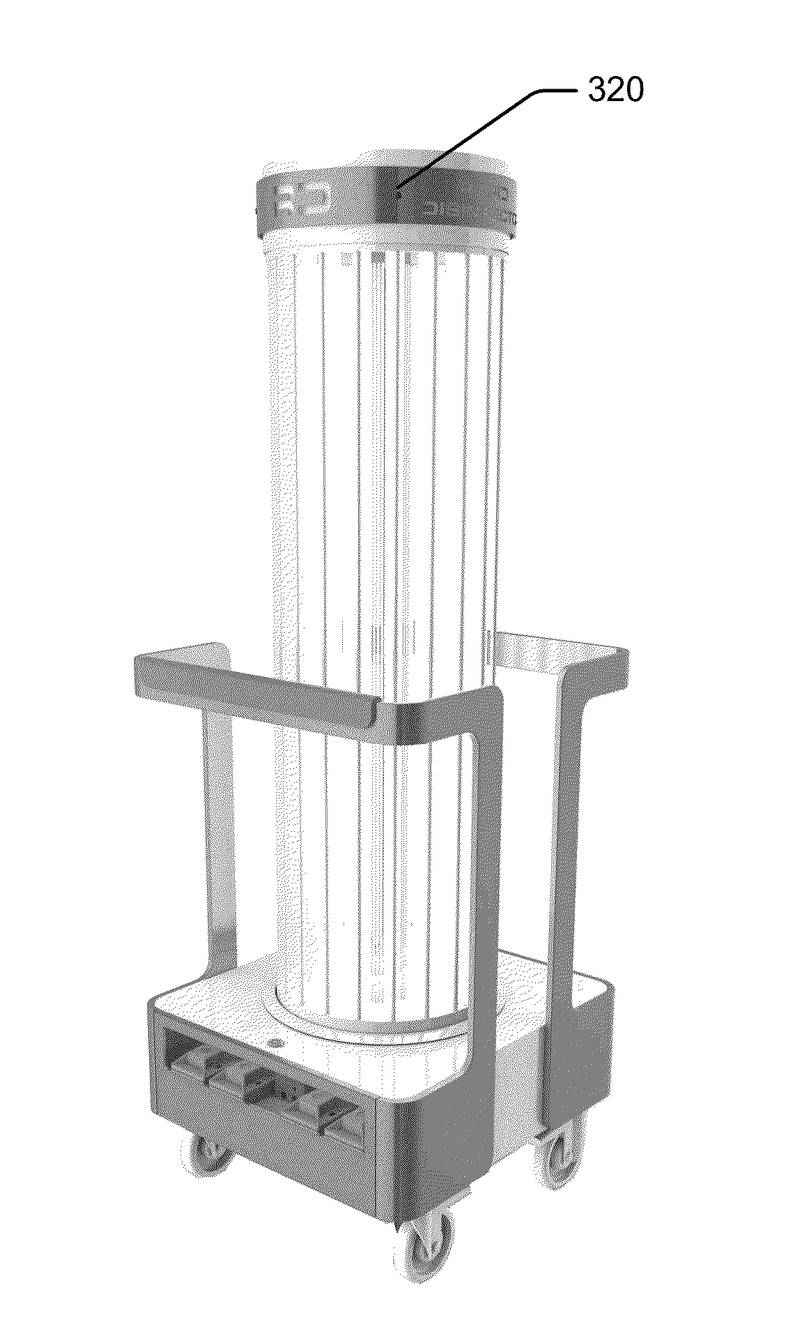
The patent is about a mobile system that delivers UV-C light to clean surfaces automatically. It is faster than other systems and can capture critical data showing that surfaces have been sterilized. UV-C disinfection leaves no harmful residue or vapors, and the room can be occupied quickly afterward.

Problems solved by technology

Even with such extreme statistics, many industry experts consider the problem to be severely underestimated.
Currently, Clostridium difficile (C. diff) is one of the most problematic pathogens in the healthcare industry.
It causes C. diff Infection (CDI) that sickens and kills humans.
Current cleaning methods, such as chemical disinfection, are not working as stand-alone practices, and additional measures need to be taken to reduce the risk to patient and healthcare professionals'.
Both of these types of equipment are unable to definitively deliver a specific dosage to a surface or volume of air because there is no measurement being taken at the location of interest.
This problem results in surfaces and air being exposed to too much, or too little, UV radiation.
In the case of over-treating, excess treatment time, which slows down the facility's operations thus adding to operating costs and reducing throughput, and excess exposure of room surfaces to UV radiation, which causes faster breakdown of the materials the surfaces are made from, may occur.
In the case of under-treating, disinfection or sterilization is not assured, which may result in reduced efficacy of disinfection procedure and increased exposure to liability.

Method used


Image

  • Room sterilization method and system
  • Room sterilization method and system
  • Room sterilization method and system

Examples


Embodiment Construction

[0061]The present disclosure may be understood more readily by reference to the following detailed description, examples, FIGURES, and claims, and their previous and following description. However, before the present devices, systems, and / or methods are disclosed and described, it is to be understood that this disclosure is not limited to the specific devices, systems, and / or methods disclosed unless otherwise specified, as such, can vary. It is also to be understood that the terminology used herein is for the purpose of describing particular aspects only and is not intended to be limiting.

[0062]As used in the specification and the appended claims, the singular forms “a,”“an” and “the” may include a plurality of referents. Thus, for example, reference to “a sensor” can include two or more such sensors.

[0063]Ranges may be expressed herein as from “about” one particular value, and / or to “about” another particular value. When such a range is expressed, another embodiment includes from ...


PUM


Abstract

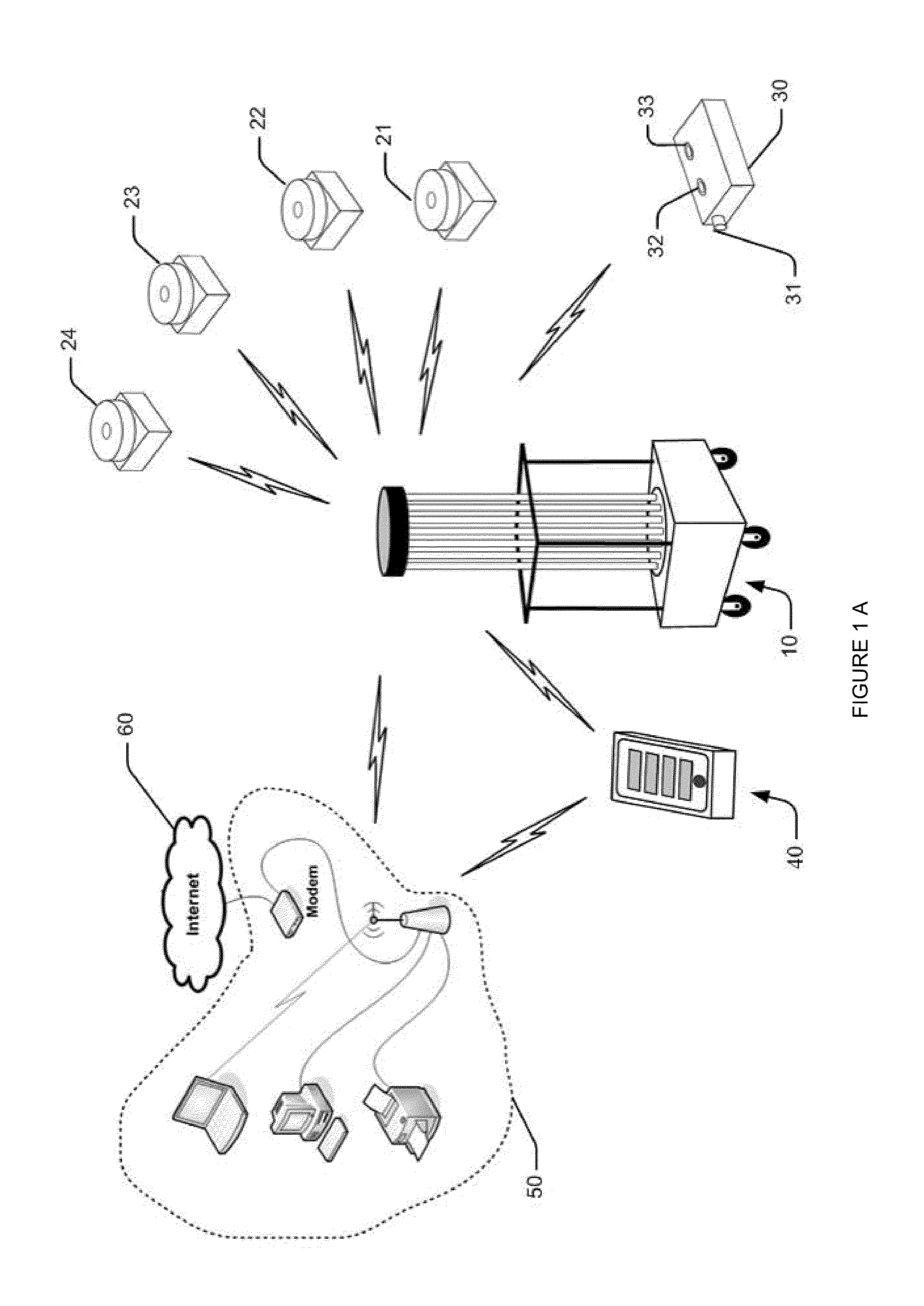
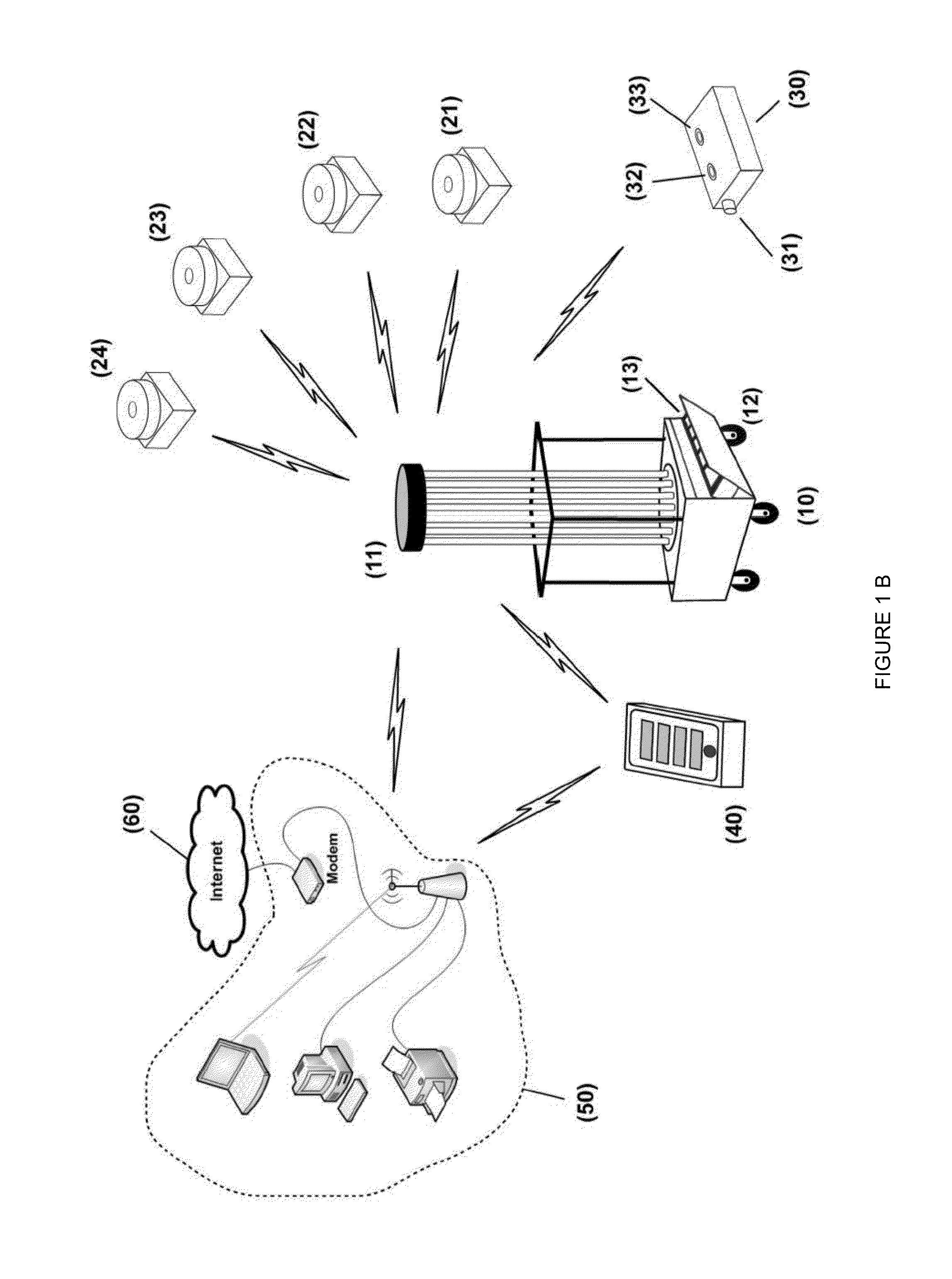
A sterilization system consisting of a mobile emitter, a sensing subsystem and a data logging subsystem is described. The emitter has one or more UV emitting lamps or devices. The sensing system comprises at least one remote UV sensor and at least one door sensor. The door sensor comprises a safety shut off door detector and may contain an emergency stop detector and arming detector to protect people from being exposed to UV energy. The system has a remote control for starting, stopping and setting system parameters which include but are not limited to: treatment time, dosage, room size, room number, unit number, floor, facility name, operator name, operator identification number, password, default dosage values, dosage, and patient identification number. The number of treatments per unit of time can be maximized because of the use of incident light measurement.

Description

CROSS-REFERENCE TO RELATED APPLICATIONS[0001]This application claims priority to U.S. Utility patent application Ser. No. 13 / 964,874 filed Aug. 12, 2013, which claims priority to U.S. Utility patent application Ser. No. 13 / 446,563 filed Apr. 13, 2012, which claims priority to U.S. Provisional Patent Application Ser. No. 61 / 475,722 filed Apr. 15, 2011.[0002]Furthermore, this application claims priority to U.S. Provisional Patent Application Ser. No. 61 / 816,530 filed Apr. 26, 2013.[0003]Furthermore, this application claims priority to U.S. Provisional Patent Application Ser. No. 61 / 887,398 filed in October 2013.[0004]All aforementioned application are hereby incorporated by reference in its entirety.FIELD OF THE INVENTION[0005]The present disclosure relates to disinfection. More specifically, the present disclosure relates to disinfection of pathogens using ultraviolet (UV) light.BACKGROUND OF THE INVENTION[0006]In the U.S. each year, more people die from hospital infections than from...

Claims


Application Information

Patent Timeline
IPC IPC(8): A61L2/24G01J1/42A61L2/10
CPCA61L2/24G01J1/429A61L2/10A61L2/202A61L2/208A61L9/015A61L9/20A61L2202/11A61L2202/14A61L2202/16A61L2202/25G01J2001/0276
Inventor TRAPANI, SAM
Owner STERILIZ
Learn More