Cylinder device and manufacturing method therefor

Inactive Publication Date: 2015-04-02
HITACHI AUTOMOTIVE SYST LTD
View PDF6 Cites 32 Cited by
  • Summary
  • Abstract
  • Description
  • Claims
  • Application Information

AI Technical Summary

Benefits of technology

[0006]The present invention has been made in view of the above-mentioned problem with the related art. The present invention provides a cylinder device and a manufacturing

Problems solved by technology

As a result, sufficient sealing may not be performed.
Meanwhile, there is a problem in that, in order to pre

Method used


Image

  • Cylinder device and manufacturing method therefor
  • Cylinder device and manufacturing method therefor
  • Cylinder device and manufacturing method therefor

Examples


Example

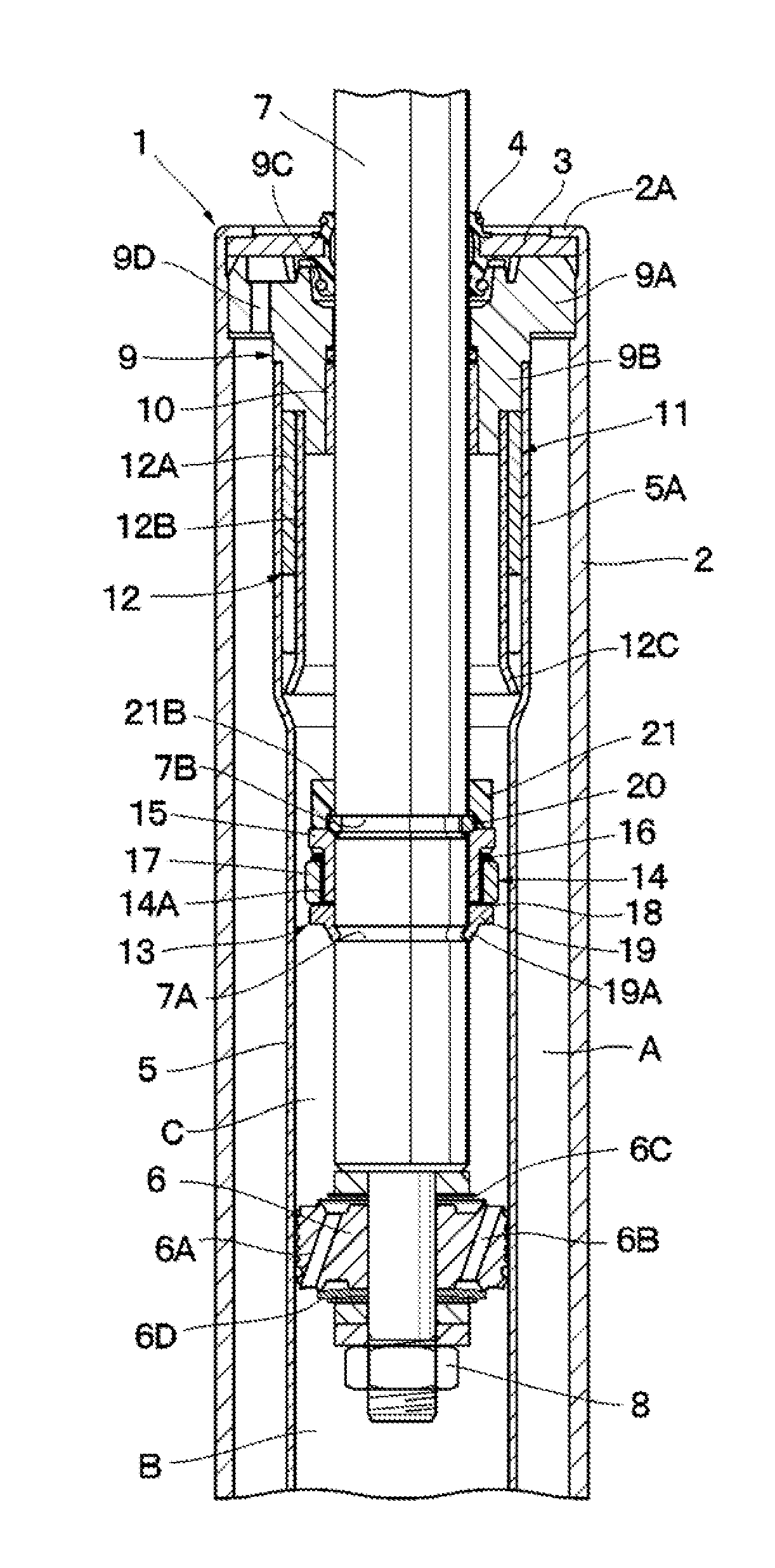
[0021]Specifically, FIGS. 1 to 3 illustrate a first embodiment of the present invention. FIG. 1 illustrates a hydraulic shock absorber 1 as a typical example of cylinder devices. The hydraulic shock absorber 1 includes an outer cylinder 2 as an outer shell thereof, an inner cylinder 5, a piston 6, a piston rod 7, a rod guide 9, and a locking mechanism 11, which are described below.

[0022]One end (lower end in FIG. 1) side of the outer cylinder 2 of the hydraulic shock absorber 1 is a closed end closed by a bottom cap (not shown), and an upper end side as another end side thereof is an open end. On the open end (upper end) side of the outer cylinder 2, there is provided a crimped portion 2A formed by bending the upper end to a radially inner side, and the crimped portion 2A retains a lid member 3 for closing the open end side of the outer cylinder 2.

[0023]In order to close the open end (upper end) side of the outer cylinder 2, the lid member 3 is formed of an annular disk, and an oute...

Example

[0080]Next, with reference to FIG. 4, description is made of a second embodiment of the present invention. The second embodiment has a feature in that the piston-side fixing portion is fixed to the outer peripheral side of the piston rod by welding means such as spot welding. Note that, in the second embodiment, the same components as those in the first embodiment described above are denoted by the same reference symbols, and description thereof is omitted.

[0081]Specifically, a piston rod 31 is configured substantially the same as the piston rod 7 described in the first embodiment, and the piston 6 (refer to FIG. 1) is coupled to a lower end side of the piston rod 31. However, the piston rod 31 in this embodiment includes an annular groove 31A for fixing a restriction ring 33 described below en an outer peripheral side of the piston rod 31, but an annular groove (equivalent to the annular groove 7A in FIG. 1) is not formed at a position of an annular stopper 32.

[0082]The annular sto...

Example

[0088]Next, FIGS. 5 to 10 illustrate a third embodiment of the present invention. This embodiment, has a feature in that the rod-guide-side fixing member of the lock piston and the cushioning member are formed integrally with each other into a single component. Note that, in the third embodiment, the same components as those in the first embodiment described above are denoted by the same reference symbols, and description thereof is omitted.

[0089]A restriction-ring integrated type cushioning member 41 (hereinafter abbreviated as integrated type cushion 41) is obtained by forming, for example, an elastic resin material into the restriction ring 20 and the cushioning member 21, which are described above in the first embodiment, integrally with each other. The integrated type cushion 41 is inserted along the outer peripheral side of the piston rod 7, and includes the cushioning portion 42 formed into a stepped cylindrical shape as a stopper for moderating impact on the rod guide 9, and...


PUM

PropertyMeasurementUnit
Digital informationaaaaaaaaaa

Abstract

A lock piston (13) of a locking mechanism (11) includes a flow path limiting-opening mechanism (14) provided on an outer peripheral side of a piston rod (7), an annular stopper (19) for supporting the flow path limiting-opening mechanism (14) from a piston (6) side, and a restriction ring (20) for restricting a fitting cylindrical body (15) of the flow path limiting-opening mechanism (14) from moving to a rod guide (9) side, the restriction ring (20) being fitted to a second annular groove (7B) of the piston rod (7). The restriction ring (20) is inserted along an outer peripheral side of the piston rod (7) from an upper end side of the piston rod (7), and fitted and fixed into the second annular groove (7B).

Description

BACKGROUND OF THE INVENTION[0001]1. Field of the Invention[0002]The present invention relates to a cylinder device to be mounted to vehicles such as a four-wheeled automobile and is suitably used for clamping vibration of the vehicle, and a manufacturing method for a cylinder device.[0003]2. Description of the Related Art[0004]In general, in vehicles such as a four-wheeled vehicle, a hydraulic shock absorber is interposed as a cylinder device between each wheel (axle side) and a vehicle body so as to reduce vibration of the vehicle (for example, refer to Japanese Utility Model Application Laid-open No. Sho 50-23533, and Japanese Utility Model Examined Publication No. Hei 4-25551). Cylinder devices of this type according to the related art include a hydraulic locking mechanism configured to cause a hydraulic cushioning effect at maximum extension of a piston rod so as to prevent full extension.[0005]By the way, in the cylinder devices according to the related art, at the time of asse...

Claims


Application Information

Patent Timeline
IPC IPC(8): F16F9/32
CPCF16F9/3221F16F9/3271F16F9/49F16F9/56F16F9/585Y10T29/4984
Inventor YAMANAKA, TERUAKI
Owner HITACHI AUTOMOTIVE SYST LTD
Why Eureka
Try Eureka