
Stacked Photodiodes for Extended Dynamic Range and Low Light Color Discrimination

a photodiode and dynamic range technology, applied in the field of image sensors, can solve the problems of limited dynamic range, conventional image sensors, and poor design of sensors, and achieve the effect of extending the dynamic range and the system dynamic rang

Inactive Publication Date: 2015-04-02
FORZA SILICON
View PDF3 Cites 25 Cited by
  • Summary
  • Abstract
  • Description
  • Claims
  • Application Information

AI Technical Summary

Benefits of technology

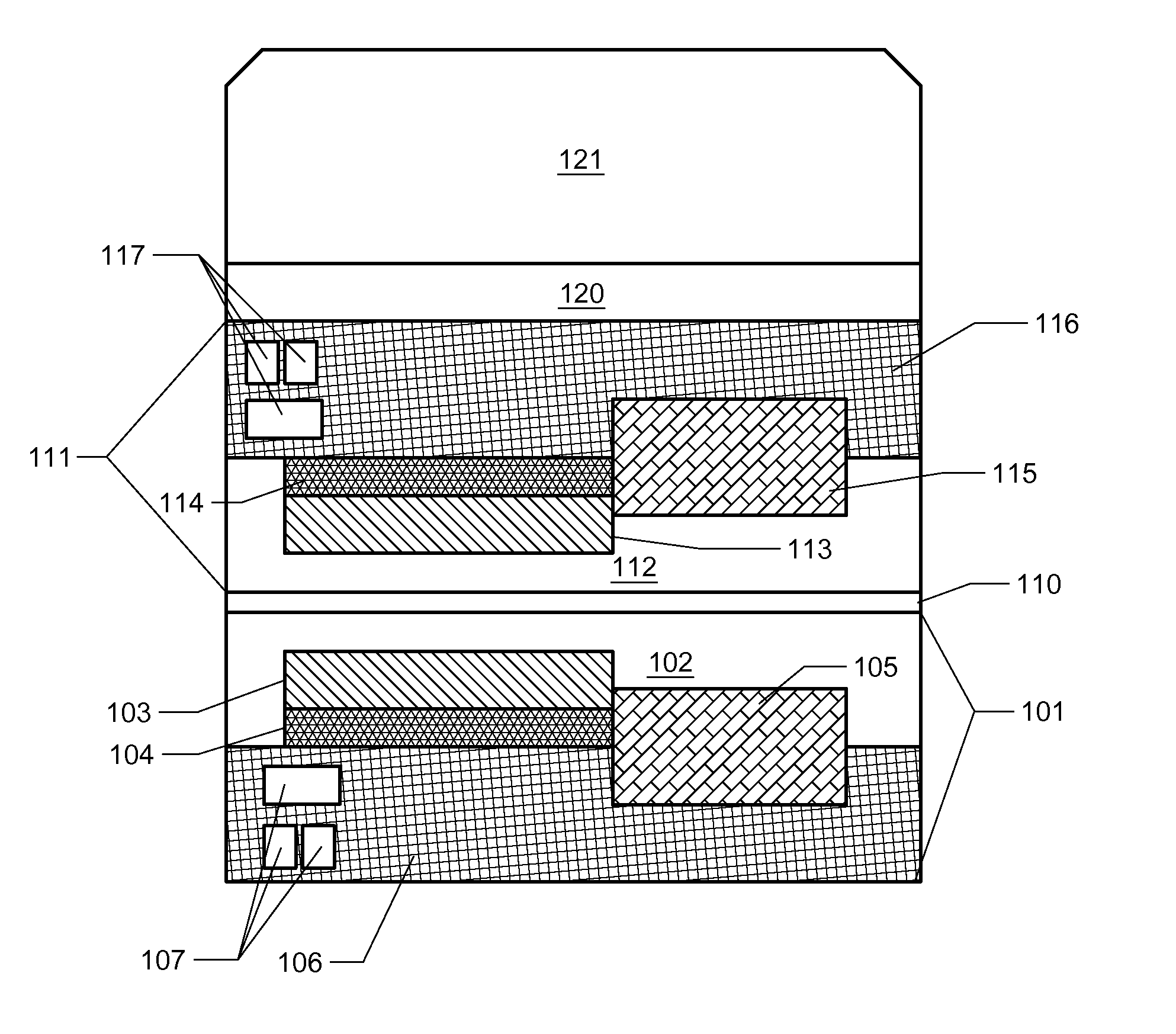
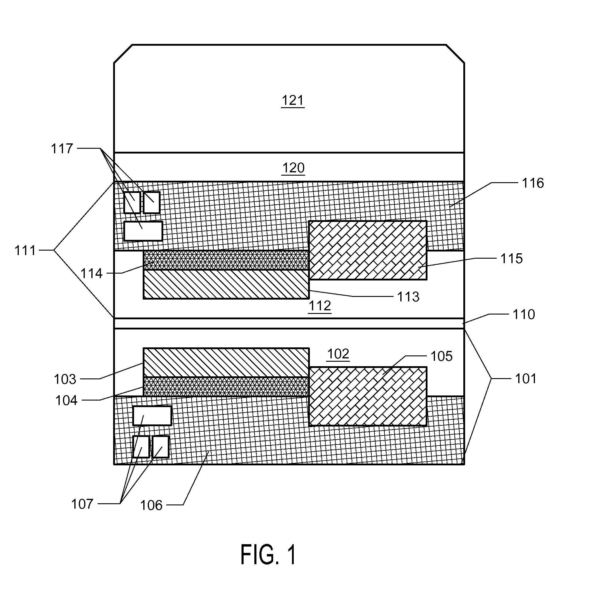
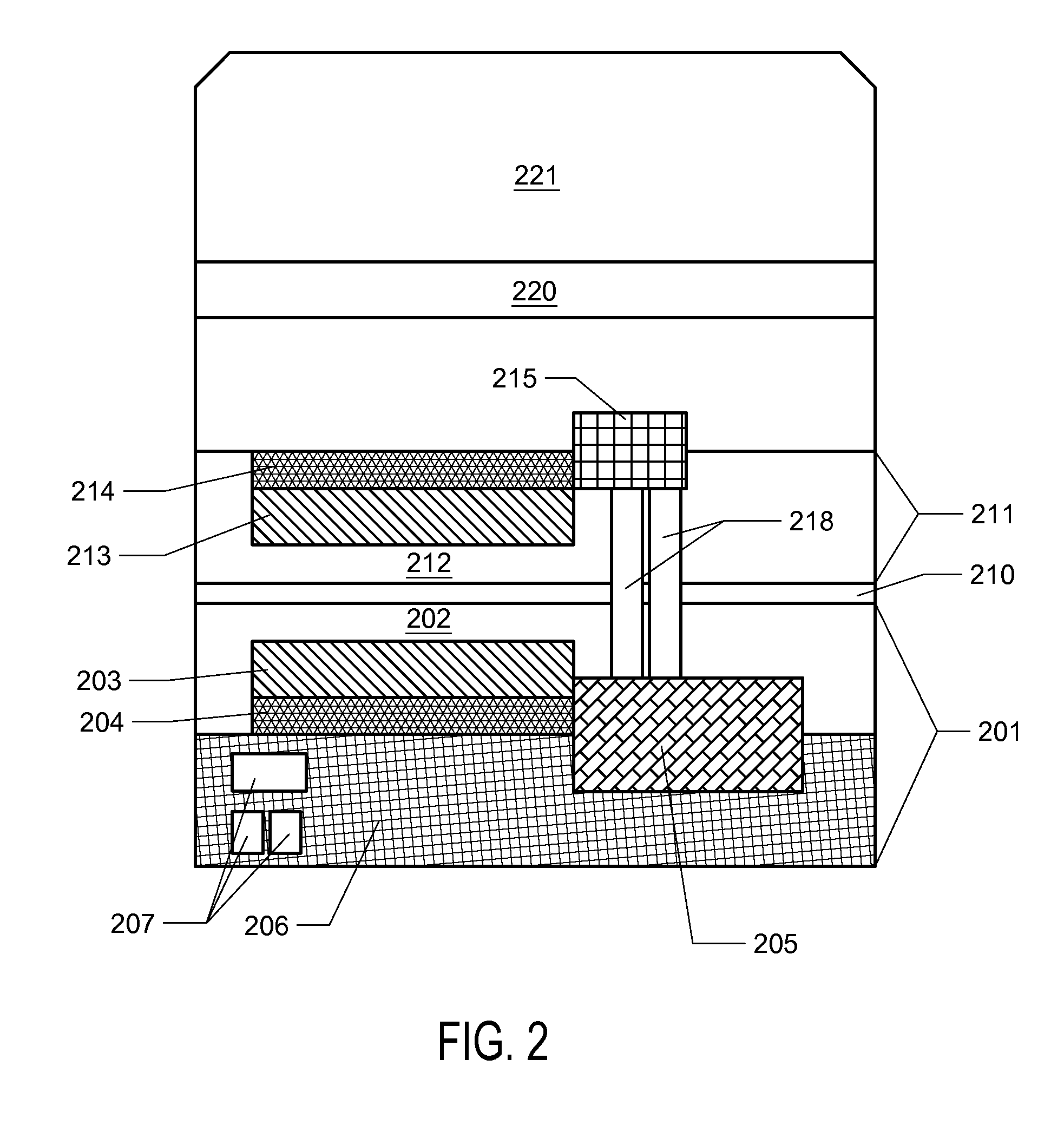
The invention describes new image sensors that have multiple photodiodes stacked on top of each other. These sensors help to extend the dynamic range of the system by using different levels of light to capture information. This design prevents saturation of the upper photodiode and allows for more accurate measurements of the light incident on the pixel. Thus, the invention enables improved image quality and performance.

Problems solved by technology

Much progress has been made in the field of image sensor design, yet current sensor designs suffer from shortcomings in various aspects.
One issue that presents problems for conventional image sensors is limited dynamic range.
When capturing an image of a scene in which some regions are highly illuminated and others are shadowed, the limited dynamic range of conventional pixel designs used in image sensors leads to a loss of information.
Unable to record the full range of tones within the scene, at a given exposure time, a conventional image sensor will typically underexpose the dark regions or overexpose the illuminated regions, such that detail in some portion of the image is lost.
Low light settings present various problems in digital photography, including color discrimination issues in addition to dynamic range issues.
However, the use of the color filter presents a significant disadvantage in a low-light setting because the filter absorbs a substantial proportion of the incoming light, leaving little signal for capture by the pixel.
Additionally, the use of a color filter array results in a loss of spatial resolution as the image is reformed.
Also, the use of a color filter array causes an increase in image noise due to artifacts inherently produced by color reconstruction processing when the missing colors in each pixel are computationally interpolated.
However, the resulting images from such sensors are monochromatic (black and white) or otherwise severely lacking in color information.
However, such sparse color methodologies require intensive image processing to estimate color, leading to substantial artifacts
Another issue encountered in low-light situations is the presence of highly illuminated areas of the image among very low light areas.
For example, within a night scene, there may be local bright spots around lighting fixtures while deeply shadowed areas nearby are very poorly lit.
Conventional sensors will often fail to capture image detail in such scenes because the well-lit areas are overexposed (i.e. pixels are saturated) and / or the dark areas are underexposed (i.e. little or no light is captured by the pixel and no image detail is resolvable).

Method used


Image

  • Stacked Photodiodes for Extended Dynamic Range and Low Light Color Discrimination
  • Stacked Photodiodes for Extended Dynamic Range and Low Light Color Discrimination
  • Stacked Photodiodes for Extended Dynamic Range and Low Light Color Discrimination

Examples


Embodiment Construction

[0014]The novel image sensors, and methods of using them, presented herein are based on the use of stacked photodiodes, wherein each photodiode is present on a separate wafer and the wafers are subsequently stacked to create the functional device. Advantageously, this allows for each of the photodiodes in the stack to be pinned. As known in the art, pinning is the use of a relatively heavily doped layer upon the photodiode's storage well region, which helps maintain the photodiode at a fixed potential and greatly decreases noise from surface interface effects.

[0015]In one implementation, the function of the photodiode stack is to provide a greatly increased overall well capacity resistant to saturation when photon flux is high, i.e., the stacked photodiodes are utilized to extend the dynamic range of the sensor. In the event that the upper photodiode becomes saturated, the lower photodiode or photodiodes will collect a measurable signal that can be used to determine total flux incid...


PUM


Abstract

The invention provides the art with novel image sensor pixel designs comprising stacked, pinned photodiodes. The stacked pinned photodiodes provide pixels with greatly increased dynamic range. The stacked pinned photodiodes also allow improved color discrimination for low light imaging, for example utilizing pixels with no overlaying color filter array.

Description

CROSS-REFERENCE TO RELATED APPLICATIONS[0001]This application claims the benefit of priority to U.S. Provisional Application Ser. No. 61 / 885,358, entitled “Stacked Photodiodes for Extended Dynamic Range,” filed Oct. 1, 2013, and to U.S. Provisional Application Ser. No. 61 / 921,632, entitled “Stacked Photodiodes for Color Determination and Extended Dynamic Range in Low Light Imaging,” filed Dec. 30, 2013, the contents of both of which are hereby incorporated by reference.STATEMENT REGARDING FEDERALLY SPONSORED RESEARCH OR DEVELOPMENT[0002]Not applicable.REFERENCE TO SEQUENCE LISTING, A TABLE, OR A COMPUTER PROGRAM LISTING COMPACT DISK APPENDIX[0003]Not ApplicableBACKGROUND OF THE INVENTION[0004]The present inventions are directed to image sensors, particularly CMOS image sensors. Much progress has been made in the field of image sensor design, yet current sensor designs suffer from shortcomings in various aspects. One issue that presents problems for conventional image sensors is limi...

Claims


Application Information

Patent Timeline
Patent Type & Authority Applications(United States)
IPC IPC(8): H01L27/146H01L25/065
CPCH01L27/14643H01L27/14621H01L27/14636H01L25/0657H01L27/14632
Inventor MANSOORIAN, BARMAKVAN BLERKOM, DANIEL
Owner FORZA SILICON
Learn More