Organic electroluminescence unit, method of manufacturing organic electroluminescence unit, and electronic apparatus

a technology of organic electroluminescence and organic electroluminescence, which is applied in the direction of solid-state devices, semiconductor devices, thermoelectric devices, etc., can solve the problems of reduced aperture ratio, device characteristics decline, and difficulty in alignment, and achieve the effect of suppressing the decline in color purity

Inactive Publication Date: 2015-04-02
JOLED INC
View PDF0 Cites 5 Cited by
  • Summary
  • Abstract
  • Description
  • Claims
  • Application Information

AI Technical Summary

Benefits of technology

[0009]It is desirable to provide an organic electroluminescence unit capable of suppressing a decline in color purity, a method of manufacturing an organic electroluminescence unit, and an electronic apparatus.

Problems solved by technology

When display units using such an organic EL device are upsized or have higher definition, alignment becomes difficult and an aperture ratio is reduced because of deformation of the mask, complicated transportation, and the like.
Accordingly, there is an issue that device characteristics decline.
However, in this technique, since the organic film is formed on the protruding portion and the recessed portion, there is an issue that it is difficult to maintain uniformity of a film thickness of the organic film.

Method used


Image

  • Organic electroluminescence unit, method of manufacturing organic electroluminescence unit, and electronic apparatus
  • Organic electroluminescence unit, method of manufacturing organic electroluminescence unit, and electronic apparatus
  • Organic electroluminescence unit, method of manufacturing organic electroluminescence unit, and electronic apparatus

Examples


first embodiment

1-1. Entire Configuration

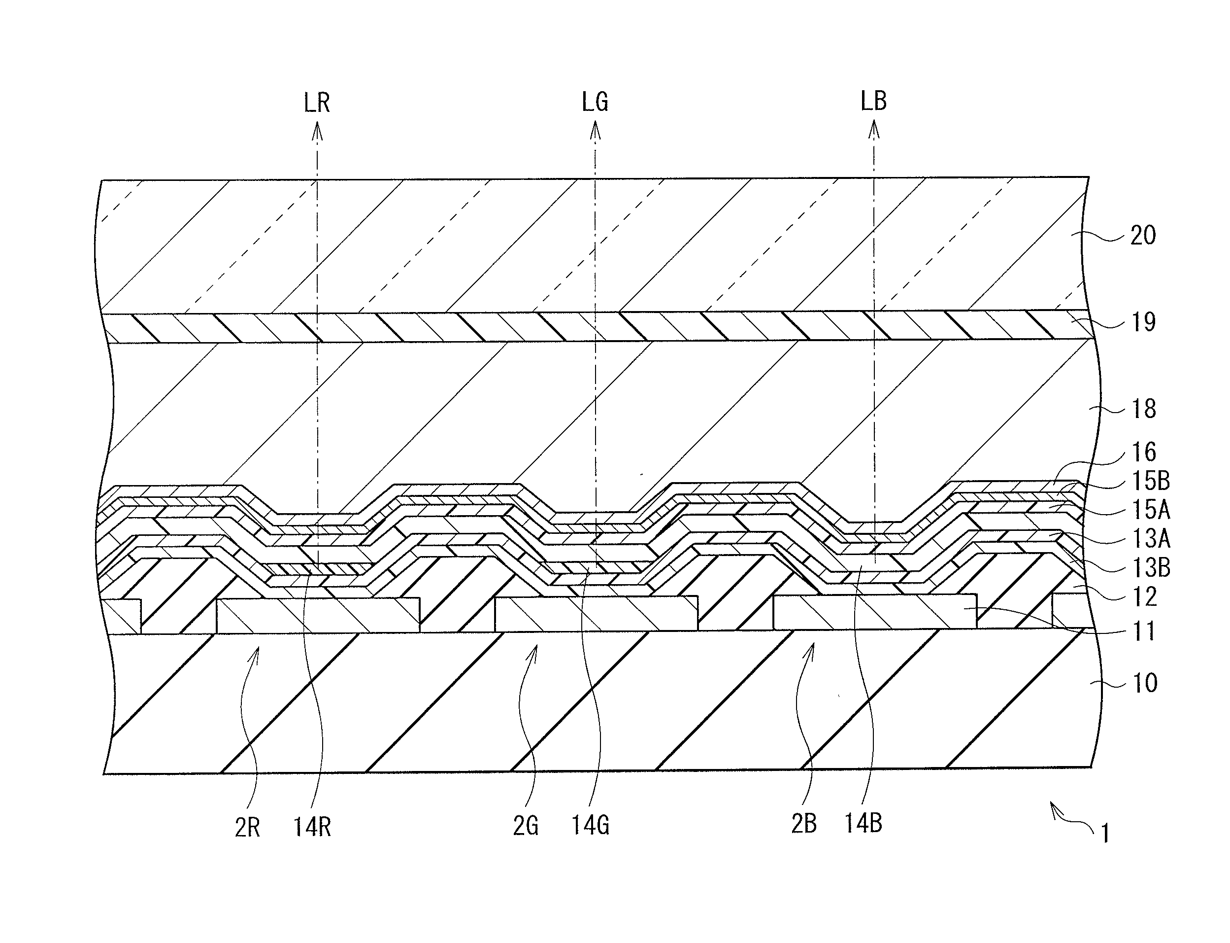
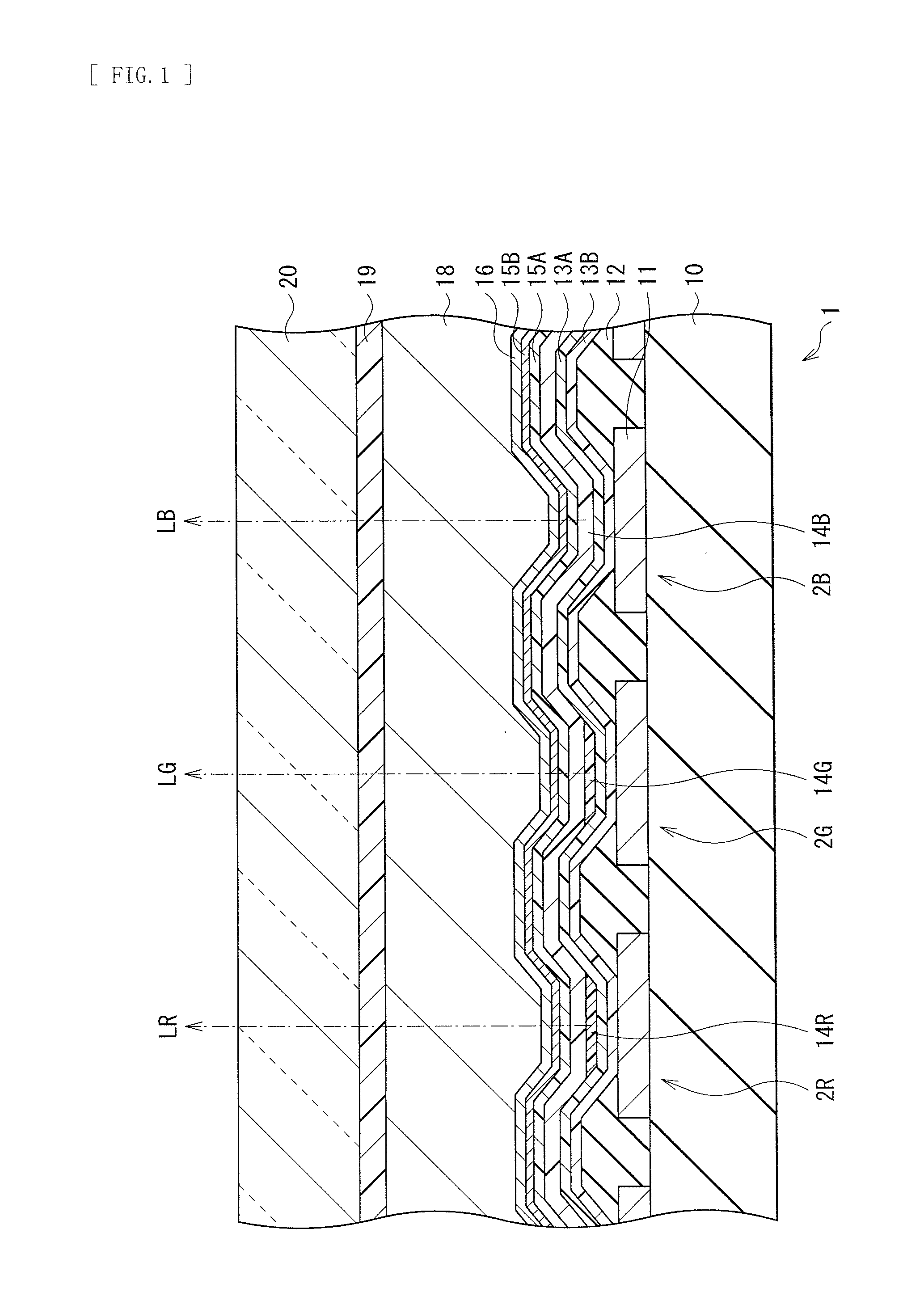
[0053]FIG. 1 illustrates a sectional configuration of an organic electroluminescence unit (a display unit 1) according to a first embodiment of the disclosure. The display unit 1 is used as, for example, an organic electroluminescence color display, and has a configuration in which a plurality of organic EL devices 2R (first organic EL devices, red pixels) emitting red light, a plurality of organic EL devices 2G (second organic EL devices, green pixels) emitting green light, and a plurality of organic EL devices 2B (blue pixels) emitting blue light are regularly arranged. These organic EL devices 2 (2R, 2G, and 2B) are covered with a protective layer 18, and are sealed by a sealing substrate 20 with an adhesive layer 19 in between. The display unit 1 is a top emission type display unit in which a combination of the organic EL devices 2R, 2G, and 2B adjacent to one another configures one pixel, and emits light LR, LG, and LB of three colors from a top surface...

second embodiment

[0116]FIG. 19 schematically illustrates laminate configurations of the organic EL devices 2R, 2G, and 2B in a display unit 2 according to the second embodiment of the disclosure. The display unit 2 according to the present embodiment is different from the first embodiment in that the charge transport layer 17 is formed as a layer common to the organic EL devices 2R, 2G, and 2B. It is to be noted that, as with the above-described first embodiment, the organic EL devices 2R, 2G, and 2B are formed on the drive substrate 10 and are sealed by the protective layer 18, the adhesive layer 19, and the sealing substrate 20 to configure a display unit.

[0117]Also in the present embodiment, each of the organic EL devices 2R and 2G have, for example, a laminate configuration in which the hole injection layer 13B, the hole transport layer 13A, the red light-emitting layer 14R or the green light-emitting layer 14G, the blue light-emitting layer 14B, the electron transport layer 15A, the electron in...

third embodiment

[0120]FIG. 20 schematically illustrates laminate configurations of the organic EL devices 2R, 2G, and 2B of a display unit 3 according to the third embodiment of the disclosure. FIGS. 21A to 21E illustrate a process of coating to collectively form a two layer, that is, the charge transport layer 17 and the green light-emitting layer 14G in the embodiment. The display unit 3 according to the embodiment is different from the above-described first embodiment in that the charge transport layer 17 and the green light-emitting layer 14G are collectively formed on the green pixel region 2G1 by coating.

[0121]In the present embodiment, as described above, the charge transport layer 17 and the green light-emitting layer 14G are collectively formed in this order on a part corresponding to the green pixel region of the hole transport layer 13A by coating. First, the red light-emitting layer 2R is formed by coating, and then the blanket 60 is coated with the solution D1g including a green light-...


PUM


Abstract

An organic electroluminescence unit includes: a plurality of light-emitting layers of different colors (14R, 14G, 14B); a first electrode (11) and a second electrode (16) applying a voltage to each of the plurality of light-emitting layers; and a charge transport layer disposed between one or more light-emitting layers of the plurality of light-emitting layers and the first electrode (11).

Description

TECHNICAL FIELD[0001]The present disclosure relates to an organic electroluminescence unit emitting light with use of an organic electroluminescence (EL) phenomenon, a method of manufacturing the same, and an electronic apparatus including the organic electroluminescence unit.BACKGROUND ART[0002]Display devices with higher performance are desired along with acceleration of development of information and communication industry. Specially, organic EL devices have been attracting attention as next generation display devices, and the organic EL devices have advantages, as self-emitting type display devices, of not only a wide viewing angle and excellent contrast but also fast response speed.[0003]The organic EL devices have a configuration in which a plurality of layers including a light-emitting layer are laminated. These layers are formed by, for example, a dry process such as a vacuum deposition method. More specifically, in a typical dry process, a mask with an opening is sandwiched...

Claims


Application Information

Patent Timeline
Patent Type & Authority Applications(United States)
IPC IPC(8): H01L27/32H01L51/50H01L51/00H01L51/56
CPCH01L27/3211H01L51/56H01L51/504H01L51/0004H01L51/5056H10K59/353H10K71/18H10K50/13H10K50/157H10K50/15H10K50/852H10K2102/351H10K59/35H10K50/125H10K50/14H10K71/00H10K71/13
Inventor IMAI, TOSHIAKITAKAGI, KAZUNARIYOSHINAGA, TADAHIKOMATSUMI, TATSUYAANDO, MAKOTO
Owner JOLED INC
Why Eureka
Try Eureka