Liquid crystal display and method of manufacturing the same

a technology of liquid crystal display and liquid crystal, which is applied in the field of liquid crystal display, can solve the problem of essentially impossible to perform a rubbing operation on the inner part of the cavity filled with liquid crystal

Inactive Publication Date: 2015-04-02
SAMSUNG DISPLAY CO LTD
View PDF5 Cites 4 Cited by
  • Summary
  • Abstract
  • Description
  • Claims
  • Application Information

AI Technical Summary

Benefits of technology

The patent describes a liquid crystal display and a method for manufacturing it. The display includes a substrate, thin film transistor, and electrodes. The method involves forming microcavities containing liquid crystal material and aligning a photo-alignment material in the microcavities using a polarized light. The photo-alignment material may include a photoisomer type material, such as a cis type photoisomer or azo benzene. The method may also include using a lower insulating layer, upper insulating layer, and capping layer. The technical effect of this patent is to provide a method for manufacturing a liquid crystal display with a wide viewing angle and improved display quality.

Problems solved by technology

In such a technique, it is essentially impossible to perform a rubbing operation on an inner part of the cavity filled with the liquid crystal such that an alignment layer is rubbed vertically to the substrate.

Method used


Image

  • Liquid crystal display and method of manufacturing the same
  • Liquid crystal display and method of manufacturing the same
  • Liquid crystal display and method of manufacturing the same

Examples


Embodiment Construction

[0036]The present disclosure will be described more fully hereinafter with reference to the accompanying drawings, in which example embodiments are shown. As those skilled in the art would realize, the described embodiments may be modified in various different ways, all without departing from the spirit or scope of the present invention. On the contrary, example embodiments introduced herein are provided to make disclosed contents thorough and complete and sufficiently transfer the spirit of the present disclosure to those skilled in the art.

[0037]In the drawings, the thickness of layers, films, panels, regions, etc., are exaggerated for clarity. It will be understood that when a layer is referred to as being “on” another layer or substrate, it can be directly on the other layer or substrate, or intervening layers may also be present. Like reference numerals designate like elements throughout.

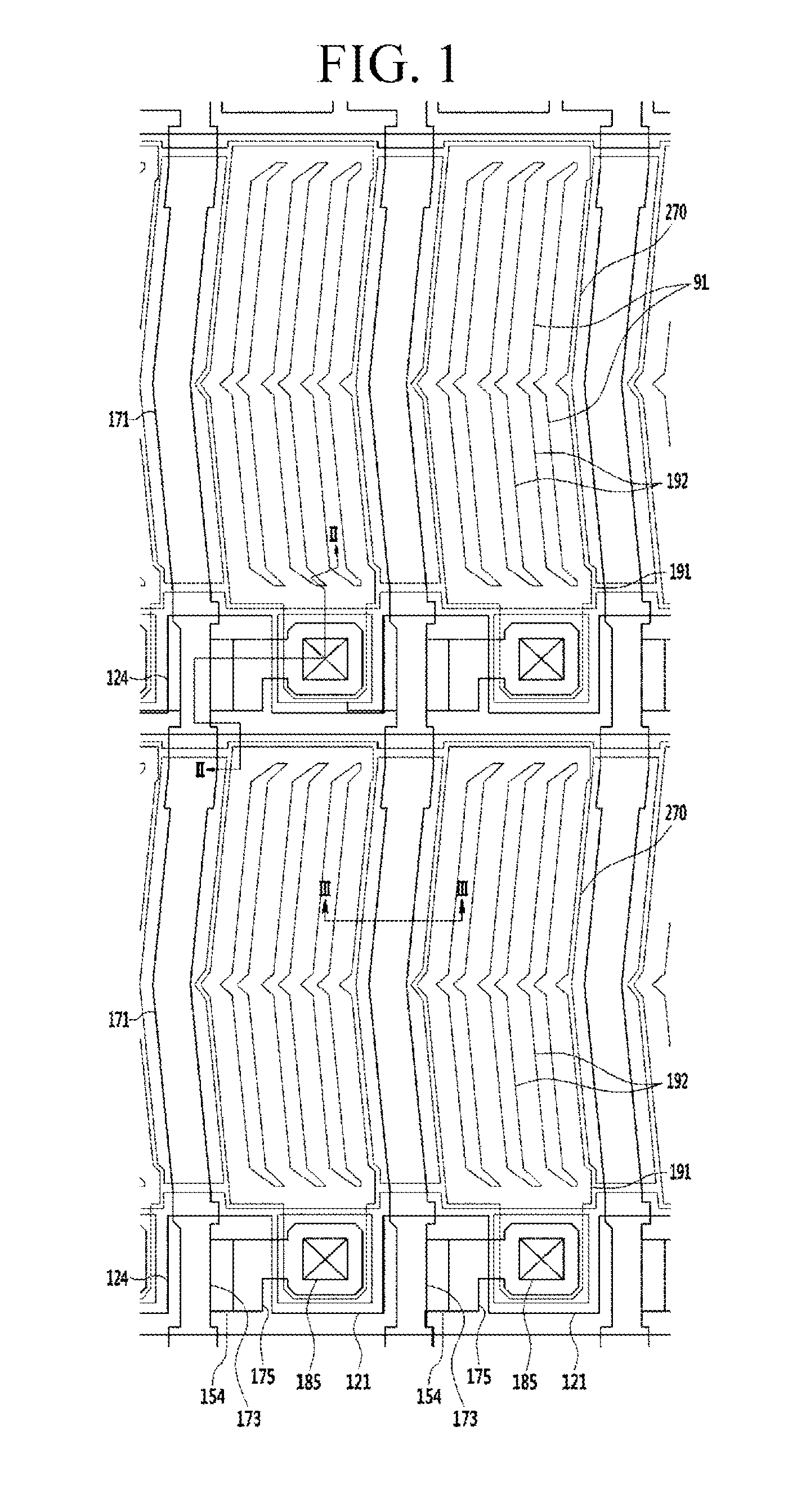
[0038]FIG. 1 is a top plan view of a liquid crystal display according to an example embodim...


PUM

PropertyMeasurementUnit
Wavelengthaaaaaaaaaa
Energyaaaaaaaaaa
Energyaaaaaaaaaa

Abstract

A liquid crystal display is provided that includes: a substrate; a thin film transistor disposed on the substrate; a protection layer disposed on the thin film transistor; a first electrode and a second electrode disposed on the protection layer; an alignment layer disposed on the second electrode; and a roof layer facing the second electrode, wherein a plurality of microcavities are formed between the second electrode and the roof layer, the microcavities include a liquid crystal material, and the alignment layer includes a photo-alignment material.

Description

CROSS-REFERENCE TO RELATED APPLICATION[0001]This application claims priority to and the benefit of Korean Patent Application No. 10-2013-0116467 filed in the Korean Intellectual Property Office on Sep. 30, 2013, the entire contents of which are incorporated herein by reference.BACKGROUND[0002](a) Field[0003]The present invention relates to a liquid crystal display and a manufacturing method thereof.[0004](b) Description of the Related Art[0005]A liquid crystal display is one type of flat panel display device that is widely used. A liquid crystal display includes two display panels on which field generating electrodes such as a pixel electrode and a common electrode are formed, and a liquid crystal layer interposed therebetween.[0006]The liquid crystal display generates an electric field in a liquid crystal layer by applying voltages to the field generating electrodes. The applied electric field determines orientations of liquid crystal molecules of the liquid crystal layer and contr...

Claims


Application Information

Patent Timeline
IPC IPC(8): G02F1/1333
CPCG02F1/1333G02F2001/133368G02F1/133788G02F1/133377G02F1/133711G02F1/1341G02F1/134309G02F1/133368G02F1/1337G02F1/1343G02F1/136
Inventor LEE, HEE-KEUNKANG, SUK HOONKIM, SANG ILKIM, YEUN TAEOH, DONG YOUBLEE, MI HWALEE, WOO JAELEE, JUN WOO
Owner SAMSUNG DISPLAY CO LTD
Why Eureka
Try Eureka