Vehicle headlamp

a technology for headlamps and headlamps, applied in the field of headlamps, can solve problems such as and achieve the effects of preventing and/or reducing contamination of the surface of light deflectors due to the adhesion of dust or volatile substances thereto, and preventing or reducing contamination of the surfa

Inactive Publication Date: 2015-04-02
KOITO MFG CO LTD
View PDF2 Cites 25 Cited by
  • Summary
  • Abstract
  • Description
  • Claims
  • Application Information

AI Technical Summary

Benefits of technology

[0010]With this configuration, since the housing isolates the light deflector from the light source which is a heat generation source, air convection near the surface of the light deflector is prevented. As a result, contamination of the surface of the light deflector due to adhesion of dust or volatile substances thereto can be prevented and / or reduced.
[0011]Exemplary embodiment of the invention can prevent or reduce contamination of a surface of a light deflector inside a vehicle headlamp.

Problems solved by technology

Dust and volatile substances, etc. carried by the air may adhere to the surface of the light deflector, which results in contamination of the surface of the light deflector.

Method used


Image

  • Vehicle headlamp
  • Vehicle headlamp
  • Vehicle headlamp

Examples


Embodiment Construction

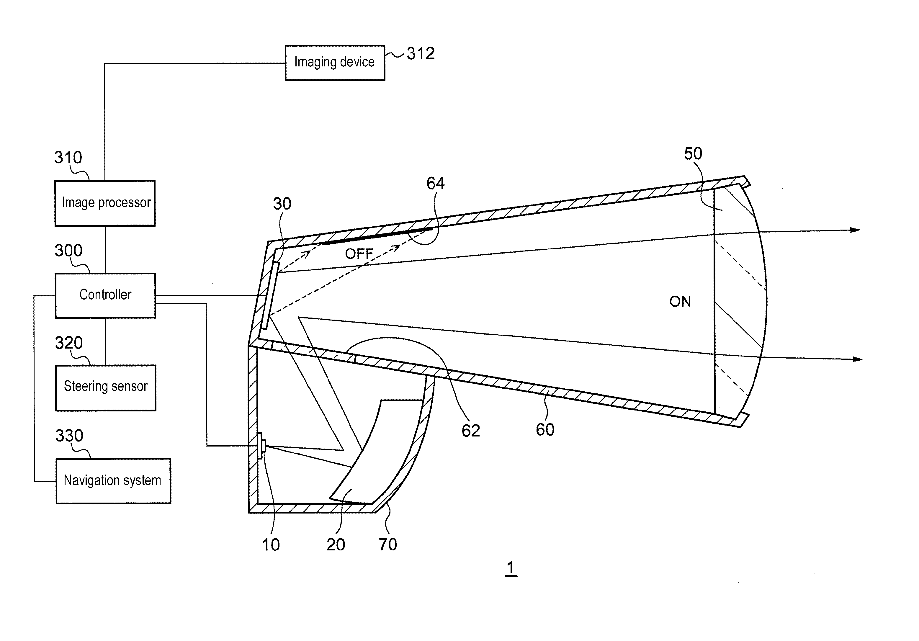
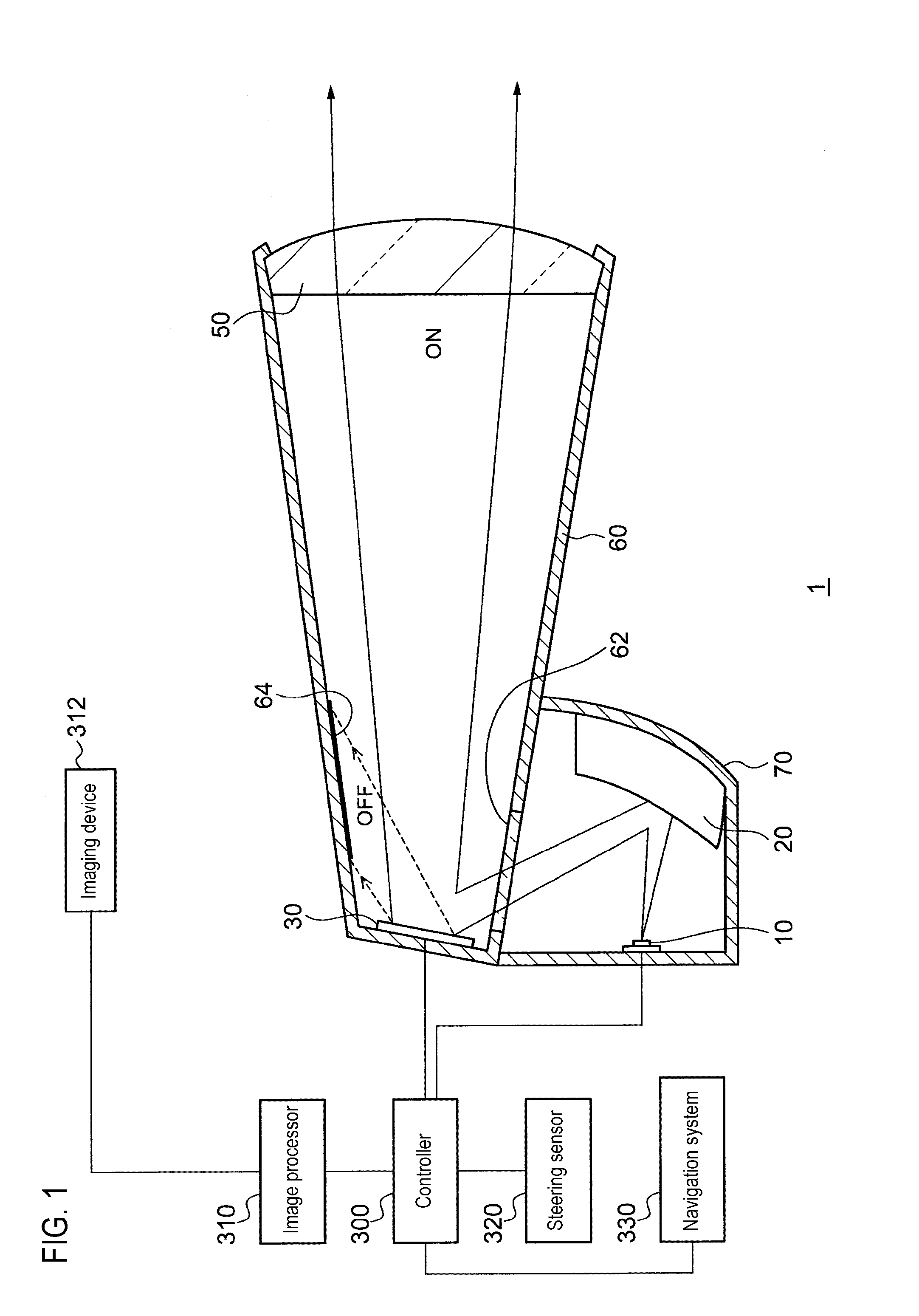
[0014]FIG. 1 is a vertical sectional view illustrating the schematic structure of a vehicle headlamp 1 according to an exemplary embodiment of the invention. The vehicle headlamp 1 is disposed on each of the left and right sides at a front portion of a vehicle. It is noted that the left and right headlamps have substantially the same configuration except that a portion of components thereof have symmetrical structure relationship therebetween in the right and left directions.

[0015]The vehicle headlamp 1 includes a first housing 60 having a substantially cylindrical shape and formed with an opening portion on a vehicle front side thereof. A projection optical member 50 is attached to the opening portion of the first housing 60.

[0016]A light source 10 may be any of a semiconductor light emitting device, such as an LED (Light Emitting Diode), an LD (Laser Diode), or an EL (Electroluminescence) device, a light bulb, an incandescent lamp (a halogen lamp), an electric-discharge lamp (a di...


PUM


Abstract

A vehicle headlamp includes a light source, a projection optical member, a light deflector, and a tube shaped housing. The projection optical member projects light, which is incident on the projection optical member, ahead. The light deflector includes a plurality of optical devices that are arrayed. The optical devices are individually switchable between a first state and a second state. In the first state, the optical devices reflect light emitted from the light source to a direction other than a direction towards the projection optical member. In the second state, the optical devices reflect the emitted light towards the projection optical member. The light deflector is disposed inside the housing. The projection optical member is disposed in an opening portion of the housing. A first portion, of the housing, intersecting a path of a light beam incident on the light deflector is transparent.

Description

CROSS REFERENCE TO RELATED APPLICATION(S)[0001]This application is based on and claims priority under 35 U.S.C. §119 to Japanese Patent Application No.2013-207163 (filed on Oct. 2, 2013), the entire contents of which are incorporated herein by reference.BACKGROUND[0002]1. Field[0003]Exemplary embodiments relate to a vehicle headlamp that employs a light deflector.[0004]2. Related Art[0005]One light deflector is provided with the large number of micro-mirror devices each of which is tiltable. Tilt angles of the micro-mirror devices are digitally switched between a first tilt angle and a second tilt angle, so that a reflection direction of light from a light source can be changed appropriately between a first reflection direction (that is, the micro-mirror devices are turned ON) and a second reflection direction (that is, the micro-mirror devices are turned OFF).[0006]JP H09-104288 A (corresponding to U.S. Pat. No. 5,938,319) describes a vehicle lighting device including a reflective ...

Claims


Application Information

Patent Timeline
Patent Type & Authority Applications(United States)
IPC IPC(8): F21S8/10B60Q1/00
CPCF21S48/1757B60Q1/0005F21S48/1388F21V14/04F21V23/0442F21S41/20F21S41/30F21S41/36F21S41/675F21W2102/00F21W2107/10B60Q1/085B60Q2300/122B60Q2300/32F21S41/365F21S45/10
Inventor YAMAMURA, SATOSHIYAGI, TAKAYUKI
Owner KOITO MFG CO LTD
Why Eureka
Try Eureka