

Bolt for gas turbine engine rotor
a gas turbine engine and bolt technology, applied in the direction of bolts, load-modified fasteners, engine fuctions, etc., can solve the problems of limiting the life of bolts, high bolt stress, and limit the advantages gained solely by alloy selection
- Summary
- Abstract
- Description
- Claims
- Application Information
AI Technical Summary
Benefits of technology
Problems solved by technology
Method used
Image

Examples
Embodiment Construction
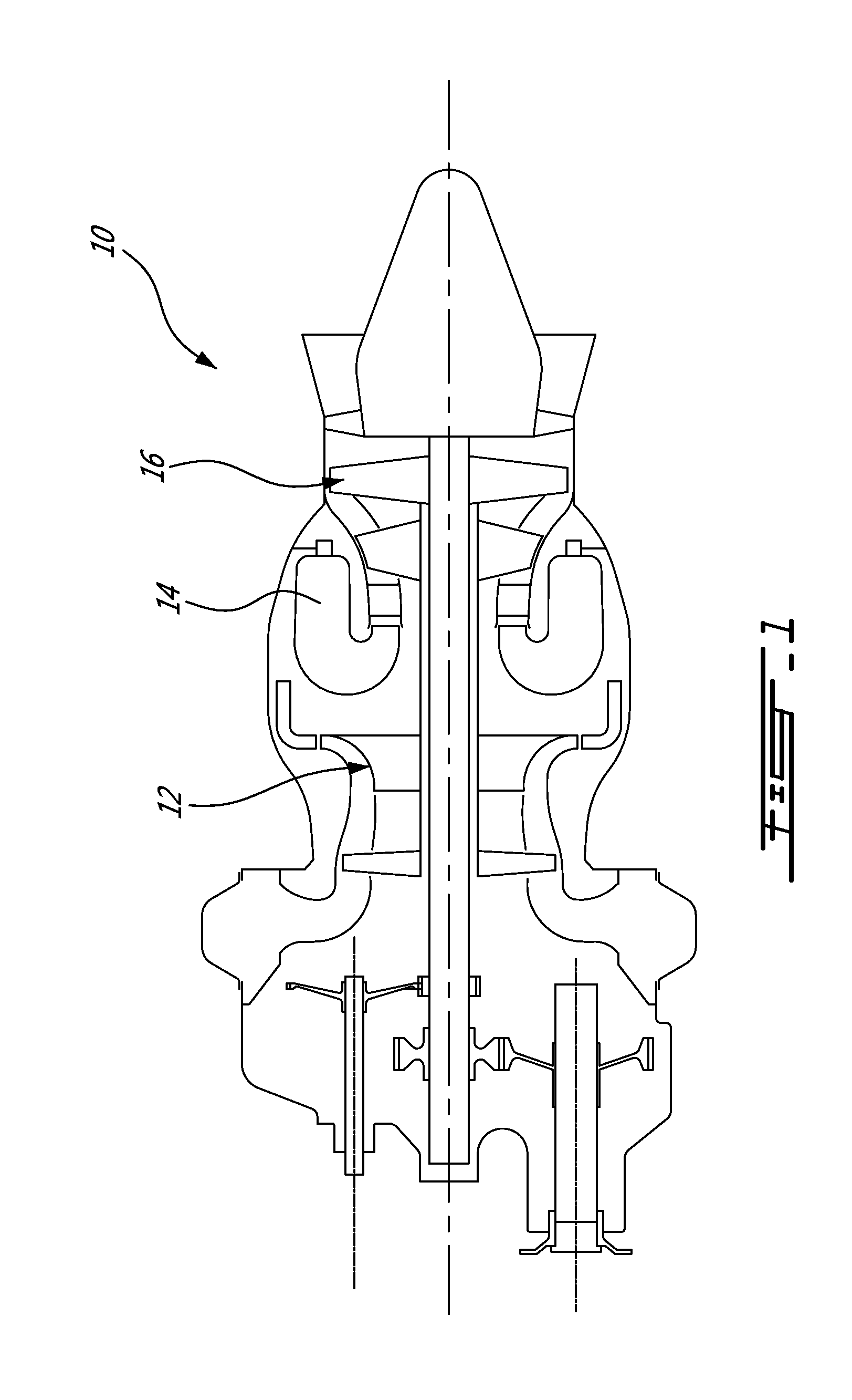
[0011]FIG. 1 illustrates an example of a turbine engine. In this example, the turbine engine 10 is a turboshaft engine generally comprising in serial flow communication, a multistage compressor 12 for pressurizing the air, a combustor 14 in which the compressed air is mixed with fuel and ignited for generating an annular stream of hot combustion gases, and a turbine section 16 for extracting energy from the combustion gases. The turbine engine terminates in an exhaust section. The compressor 12 and turbine section 16 include rotary components, or rotors, which revolve at high speeds around the main axis 11 of the engine.
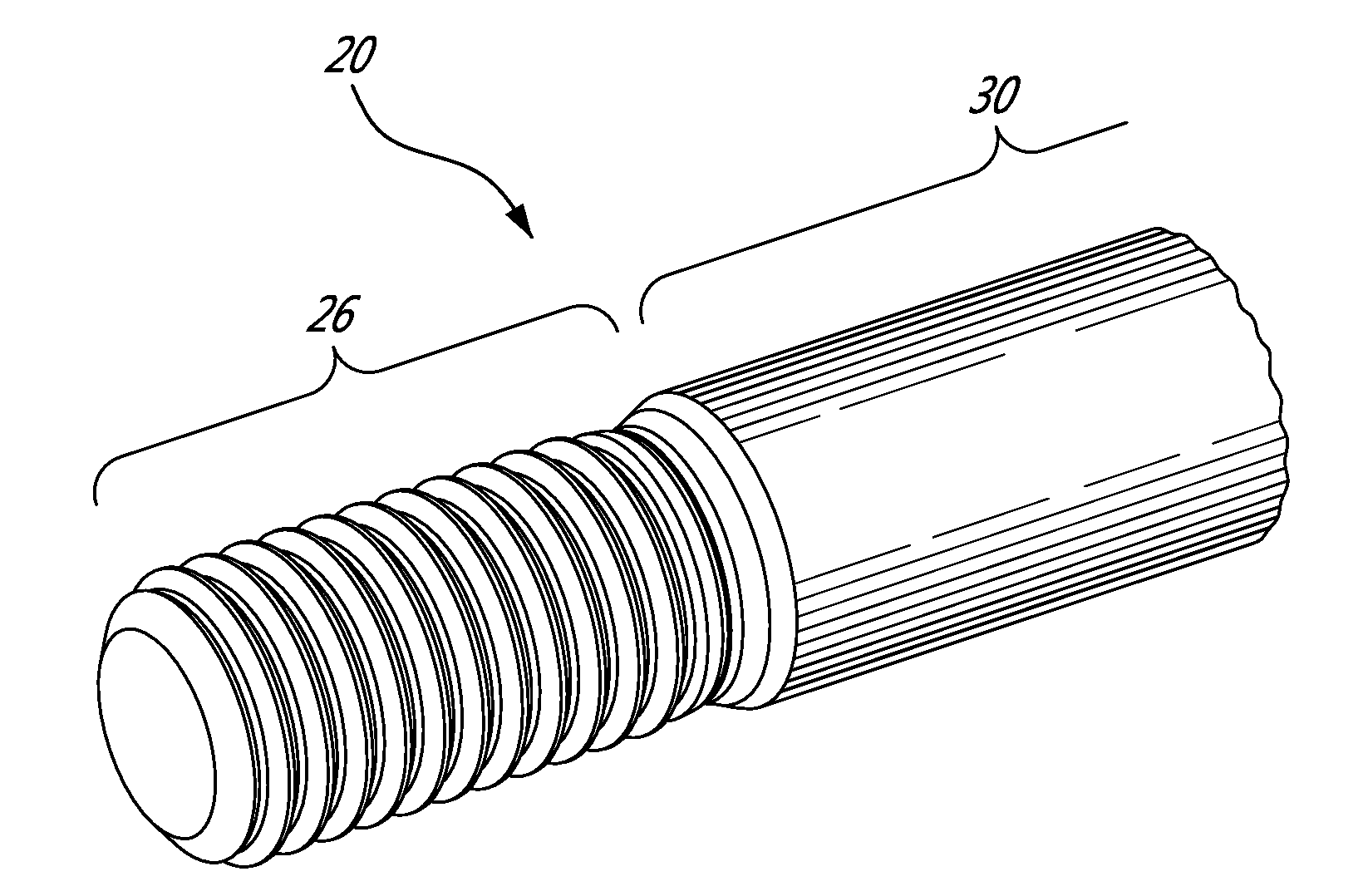
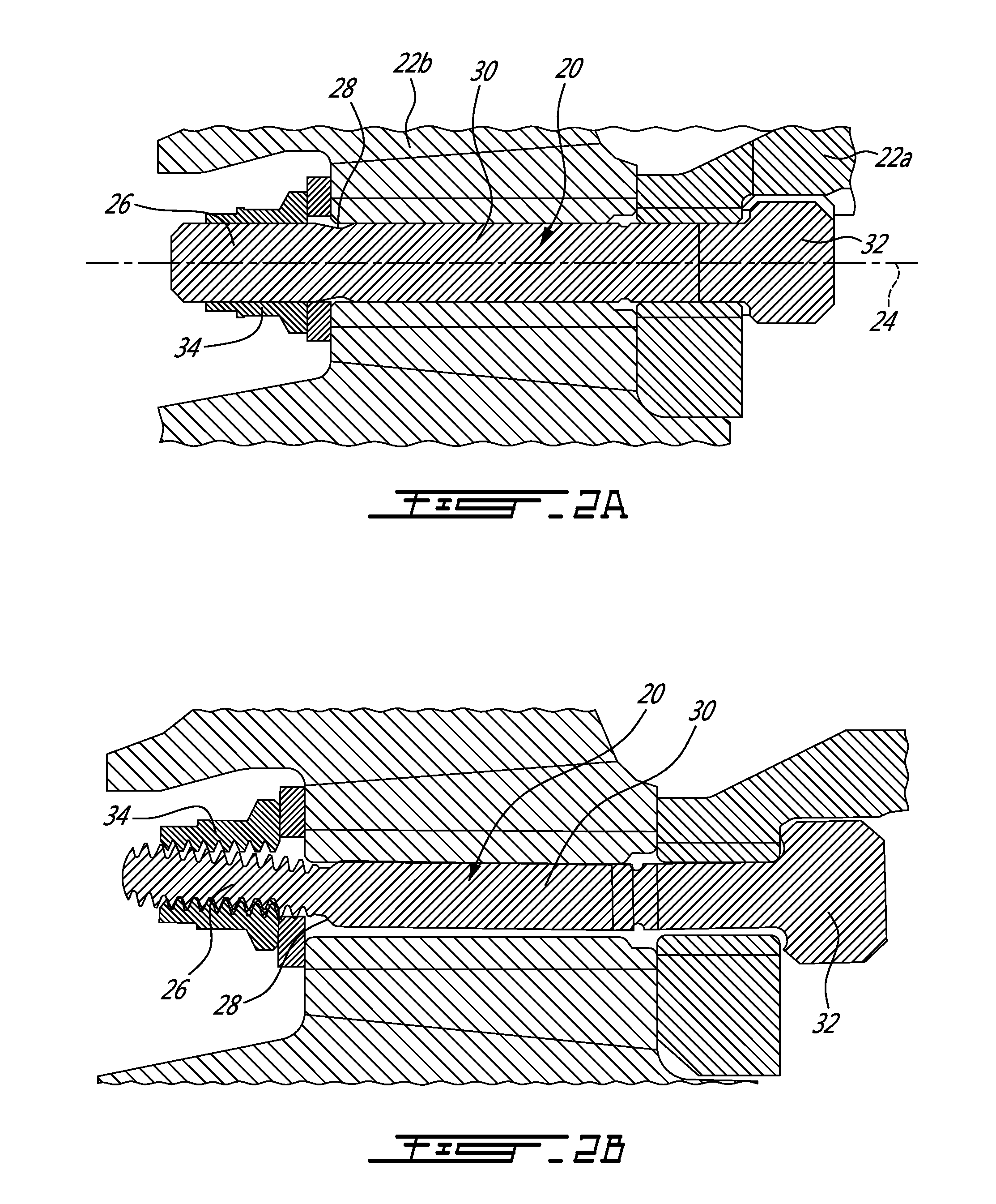
[0012]FIG. 2A shows a bolt 20 having a thru bolt configuration used in clamping two rotor components 22a, 22b of gas turbine engine 10. More specifically, the bolt 20 is used to clamp a mixed flow rotor and the impeller flange together, in this specific embodiment. The bolt 20 can generally be seen to have a bolt axis 24, which is parallel to and spaced apart from th...
PUM
 Abstract
Description
Claims
Application Information