Motor-driven compressor

a motor-driven compressor and compressor technology, applied in the direction of electric generator control, dynamo-electric converter control, dynamo-electric gear control, etc., can solve the problems of increasing the frequency increasing the noise of switching elements, and increasing the number of switching of switching elements, so as to reduce the heat generation of switching elements and minimize noise.

Inactive Publication Date: 2015-04-02
TOYOTA IND CORP
View PDF6 Cites 5 Cited by
  • Summary
  • Abstract
  • Description
  • Claims
  • Application Information

AI Technical Summary

Benefits of technology

[0005]Accordingly, it is an objective of the present invention to provide a motor-driven compressor that suppresses heat generation in switching elements, while minimizing the noise due to the switching of the switching elements.

Problems solved by technology

However, since the two-phase modulation control has a greater fluctuation in the current of the electric motor compared to the three-phase modulation control, a greater noise is generated at switching of the switching elements.
However, the higher the carrier frequency, the more frequent the switching of the switching elements becomes.
If the switching elements are heated to an excessively high temperature, the switching elements can be damaged.

Method used


Image

  • Motor-driven compressor
  • Motor-driven compressor
  • Motor-driven compressor

Examples


Embodiment Construction

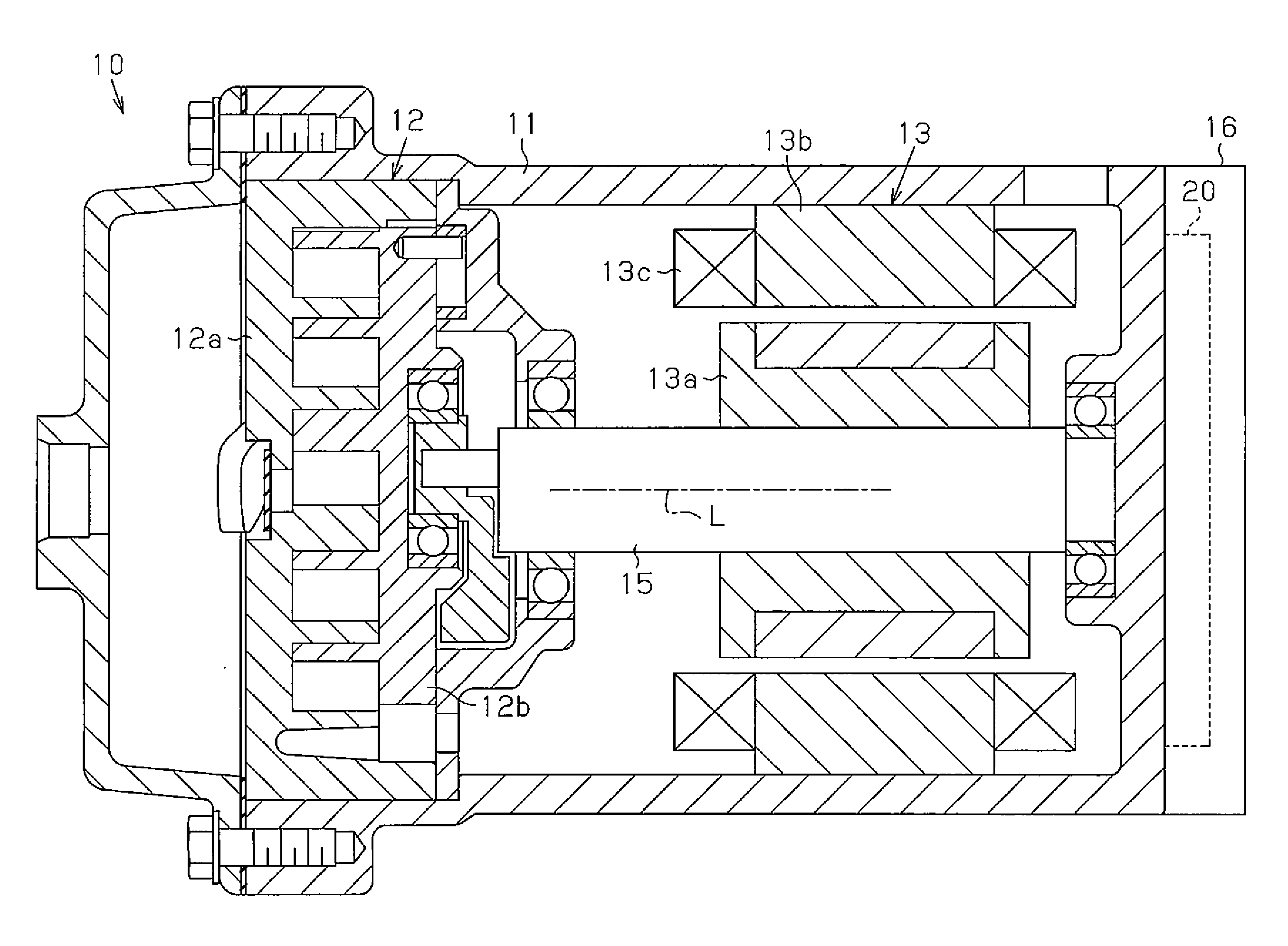
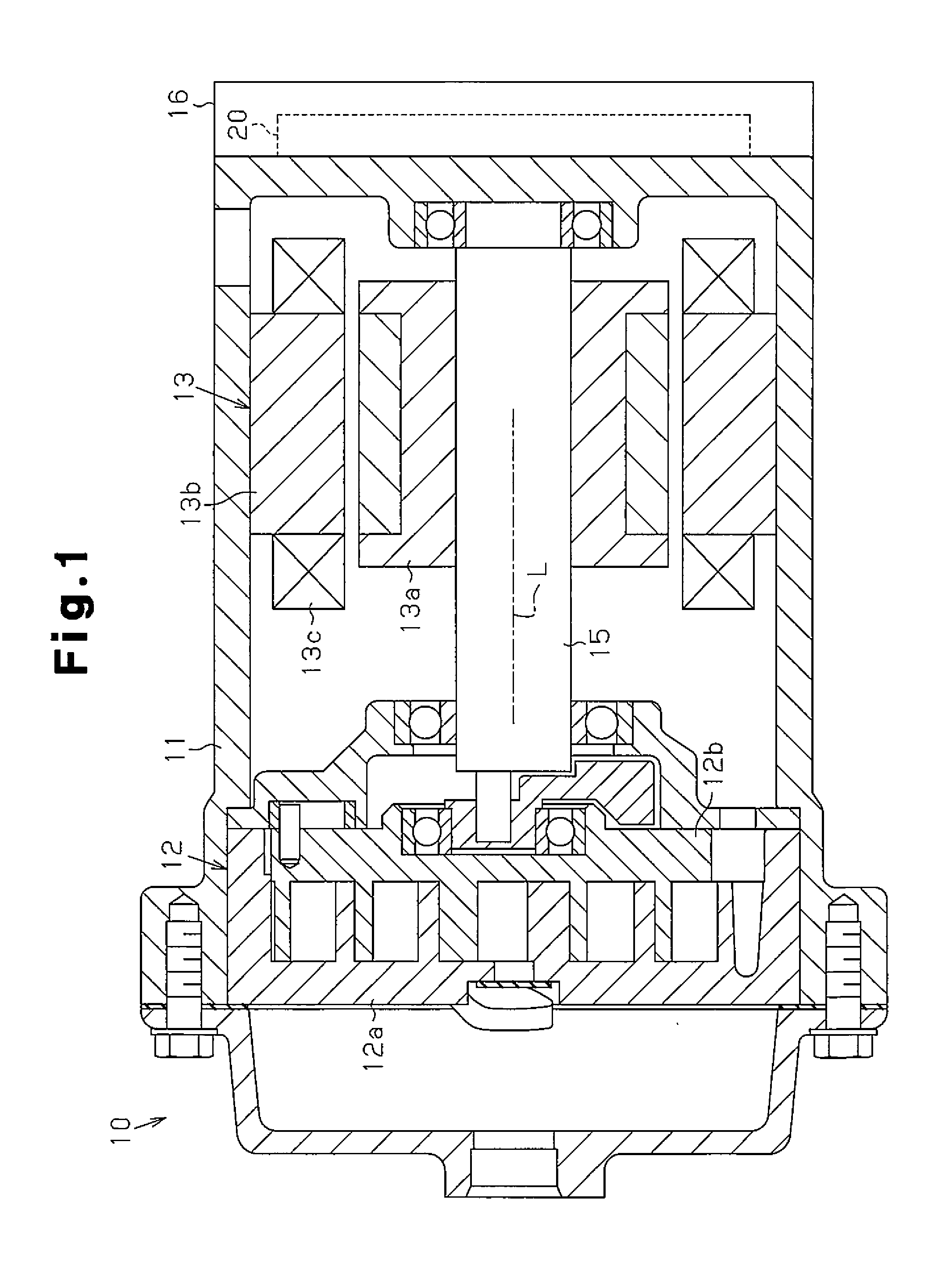
[0017]A motor-driven compressor 10 according to one embodiment will now be described with reference to FIGS. 1 to 6. The motor-driven compressor 10 of the present embodiment is mounted on a vehicle and employed for a vehicle air conditioner.

[0018]As shown in FIG. 1, the motor-driven compressor 10 has a housing 11, which accommodates a compression portion 12 and an electric motor 13. The compression portion 12 compresses and discharges refrigerant, and the electric motor 13 drives the compression portion 12. The compression portion 12 includes a fixed scroll 12a, which is fixed in the housing 11, and an orbiting scroll 12b, which is arranged to be opposed to the fixed scroll 12a. The electric motor 13 includes a rotor 13a and a stator 13b. The rotor 13a is fixed to a rotary shaft 15 to rotate integrally with the rotary shaft 15, and the stator 13b is fixed to the inner circumferential surface of the housing 11.

[0019]A cover 16 is attached to the bottom wall of the housing 11. The cov...


PUM


Abstract

A motor-driven compressor includes a compression portion, an electric motor, a motor drive circuit having switching element, a temperature detector, and a switcher, which switches the drive mode of the motor drive circuit. When acquiring information indicating that the temperature detected by the temperature detector has increased and reached a first preset temperature, the switcher switches the drive mode of the motor drive circuit from a first drive mode to a second drive mode. Also, when acquiring information indicating that the temperature detected by the temperature detector has increased and reached a second preset temperature, which is higher than the first preset temperature, the switcher switches the drive mode of the motor drive circuit from the first drive mode or the second drive mode to a third drive mode.

Description

BACKGROUND OF THE INVENTION[0001]The present invention relates to a motor-driven compressor.[0002]For example, a motor-driven compressor disclosed in Japanese Laid-Open Patent Publication No. 2005-201108 includes a compression portion, which compresses and discharges refrigerant, an electric motor, which drives the compression portion, and a motor drive circuit, which drives the electric motor.[0003]In general, the pulse width modulation (PWM) control is employed as a method for controlling electric motors. The motor drive circuit controls the drive voltage of the electric motor through the pulse width modulation. Specifically, a PWM signal is generated with a high-frequency triangular wave signal, which is referred to as a carrier wave, and a voltage command signal for commanding a voltage. Based on the PWM signal, the switching elements perform switching, so that the motor drive circuit converts a DC voltage to an AC voltage. The obtained AC voltage is applied, as the drive voltag...

Claims


Application Information

Patent Timeline
Patent Type & Authority Applications(United States)
IPC IPC(8): F04C28/08F04C28/28F04C23/02F04C18/02F04B39/00H02P21/05H02P23/04H02P27/06H02P27/08
CPCF04C28/08F04C23/02F04C28/28F04C18/0215H02P23/0027H02P27/085H02M7/5395H02P6/085H02P29/68F04B35/04F04B49/06
Inventor FUKASAKU, HIROSHINAGATA, YOSHIKI
Owner TOYOTA IND CORP
Why Eureka
Try Eureka