Shaft Seal Pressure Compensation Apparatus

a compensation apparatus and seal technology, applied in the direction of machines/engines, liquid fuel engines, borehole/well accessories, etc., can solve the problems of excessive seal leakage, premature contamination of transmission lubricant, seal leakage, etc., and achieve the effect of minimizing differential pressur

Inactive Publication Date: 2015-04-09
HARRIER TECHNOLOGIES INC
View PDF12 Cites 1 Cited by
  • Summary
  • Abstract
  • Description
  • Claims
  • Application Information

AI Technical Summary

Benefits of technology

[0008]The present invention addresses the excessive differential pressure in one set of seals, having as its objective, the balancing of fluid pressures, including ambient pressure, for all seals, both upper and lower, thereby minimizing the differential pressure between all seals and transmission they protect. An objective related to the foregoing is the extension of times related to maintenance and repair of existing components which might otherwise occur due to contamination and leakage of fugitive fluids.

Problems solved by technology

Because of this, this type of seal leaks, the rate of leakage depending principally upon the pressure differential across the seals.
This significant pressure differential can result in excessive seal leakage, and premature contamination of the transmission lubricant and subsequent transmission failure.

Method used


Image

  • Shaft Seal Pressure Compensation Apparatus
  • Shaft Seal Pressure Compensation Apparatus
  • Shaft Seal Pressure Compensation Apparatus

Examples


Embodiment Construction

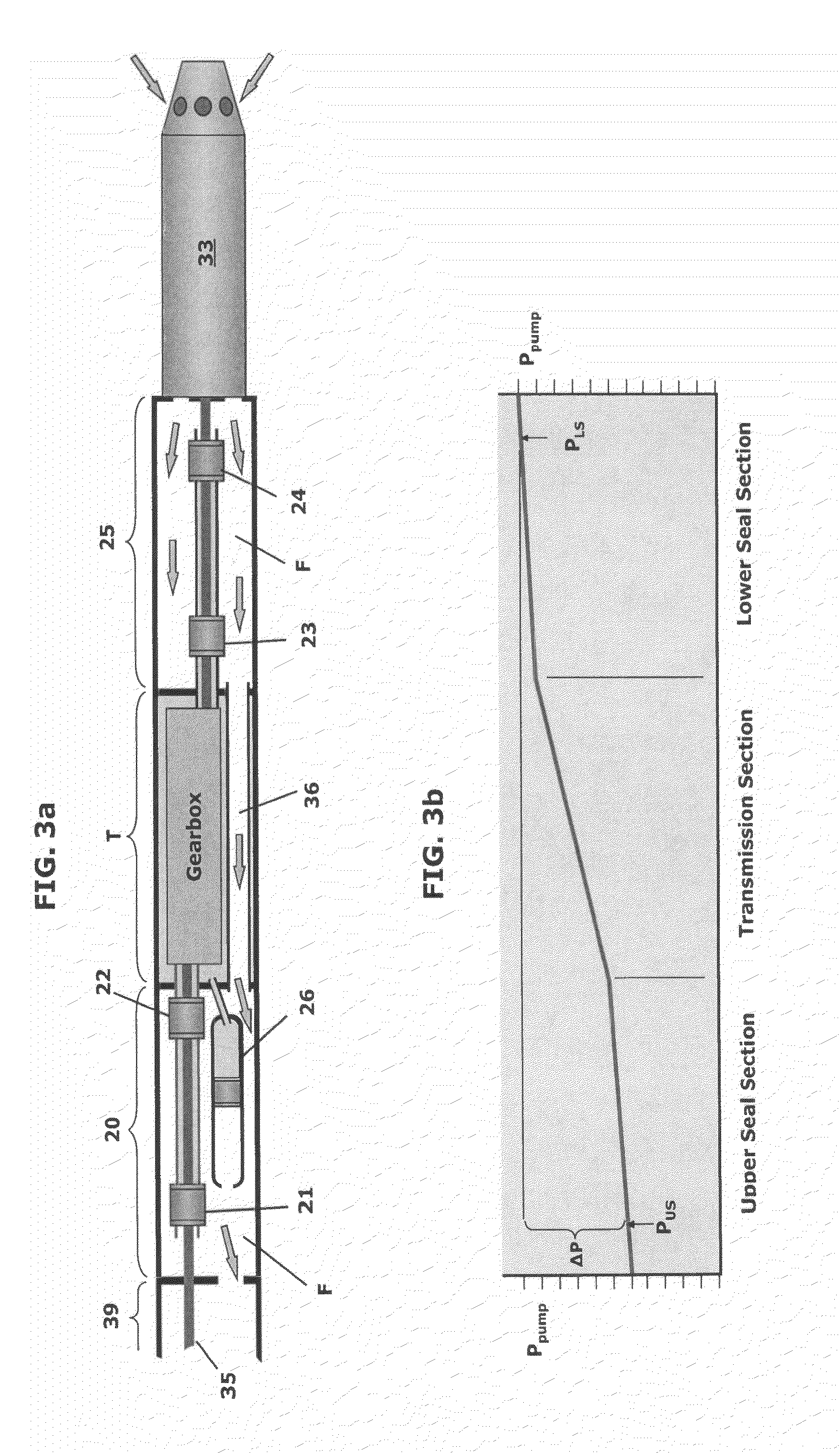
[0018]Referring now to the drawings, and initially to FIG. 3a, the current layout of a GCP, with the current configuration of the upper and lower seal sections, 20 and 25, respectively, is shown. The multi-stage centrifugal pump 33 is driven via a rotating drive rod string 35, and a step up, or speed-increasing transmission T. The high pressure production fluid F discharged from the pump flows through the lower seal section 25 and into the D-tube flow channels 36, through the transmission section T, into and through the upper seal section 20, into the receiver 39 and then into the tubing (not shown) on its way to the surface, as indicated by the arrows.

[0019]The flow of production fluid along this path between the pump 33 and the receiver 39 results in a frictional pressure drop that can exceed 5 psi for large flow rates (˜5000 bfpd). This pressure drop is shown graphically on FIG. 3b. The pressure drop through the transmission section D-tubes 36 is the steepest due to the restricte...


PUM


Abstract

A pressure compensating system that minimizes the pressure differences across multiple shaft seals in a rod driven downhole pumping apparatus. The system balances the pressures across the seals by forcing the external pressure of all seals and compensators to be equal to the highest external pressure in the apparatus, made possible by the appropriate use of labyrinth-type seals. A bleed valve assembly which allows free flow of fluid into the pressure compensating system, but restricts the rate of fluid outflow from the system in case of shut-in of the pump, to limit the potential of rapid opening and closing of the mechanical shaft seals.

Description

[0001]Applicant claims the benefits of provisional application Ser. No. 61 / 888,131, filed Oct. 9, 2013. The present invention relates, in a general sense, to pressure compensation apparatus, with particular emphasis on minimization of pressure differentials across shaft seals in downhole elements.BACKGROUND OF THE INVENTION[0002]Many mechanical devices which utilize a lubricated rotating shaft as a component require seals on those shafts to either contain a pressurized fluid, e.g., for a shaft driving a pump, or to isolate one component from contamination, or both.[0003]In the case of downhole rotating equipment, such as an electrical submersible pump (ESP), or a geared centrifugal pump (GCP), the rotating shafts require seals, principally to protect the fluids inside sensitive components, such as the electric motor (ESP) or the transmission (GCP), from contamination such as from production fluids.[0004]The seals in these two applications are not called upon to withstand significant...

Claims


Application Information

Patent Timeline
Patent Type & Authority Applications(United States)
IPC IPC(8): E21B43/12
CPCE21B43/126E21B4/003E21B43/128F04D29/106
Inventor MORROW, WILLIAM BRUCE
Owner HARRIER TECHNOLOGIES INC
Why Eureka
Try Eureka