Method of Fully Expelling Compressed Gas From a Tank

a compressed gas and tank technology, applied in the direction of container filling under pressure, vessel construction details, transportation and packaging, etc., can solve the problems of high cost, high labor intensity, and insufficient safety of the system, so as to reduce the transfer differential pressure and increase the safety level of the system

Active Publication Date: 2016-12-08
MOSZKOWSKI MARC +1
View PDF1 Cites 1 Cited by
  • Summary
  • Abstract
  • Description
  • Claims
  • Application Information

AI Technical Summary

Benefits of technology

[0011]Another advantage of this invention is that the connectors can easily be backfilled with either a liquid or nitrogen before being safely disconnected.
[0013]Another objective of this invention is minimizing the transfer differential pressure so that it enables the installation of safety devices on the tanks so that in case of a collision when the piping on top of the tanks is ripped off or any other type of leakage, a safety mechanism can quickly shut down the flow of gas trying to exit the tank through the broken piping, substantially increasing the safety level of the system.

Problems solved by technology

A second problem exists that if the tanks at the market have an intermediate pressure such as 600 p.s.i.
This means that approximately 60% of the product transported remains undelivered.
The gas compressors are expensive and expensive to operate.
However, the higher cost in many cases is the time tying up the access to the terminal while they are being pumped out.
Especially in the case of ocean going ship terminals, the dock time is an expensive charge.
In the case of trucks, the total volume of stranded gas is not large, however, in very large ocean going vessels, the amount of gas stranded by contemporary methods can be very large.
Another problem associated with conventional methods of transportation are nefarious thermal issues.
If the receiving tank pressure is zero and the transportation tank pressure is 3,000 p.s.i., for example, the instantaneous temperature drop upon opening the valve would be 84 degrees K or 151 degrees F., with very bad consequences if there was any water or foreign gases or liquids in the transportation tank.
In addition to substantial thermal risks, the 3000 p.s.i. on the transportation tank and 0 p.s.i. in the receiving tank will average out to be 1500 p.s.i. in both tanks, with half of the gas being deliver

Method used


Image

  • Method of Fully Expelling Compressed Gas From a Tank
  • Method of Fully Expelling Compressed Gas From a Tank
  • Method of Fully Expelling Compressed Gas From a Tank

Examples


Embodiment Construction

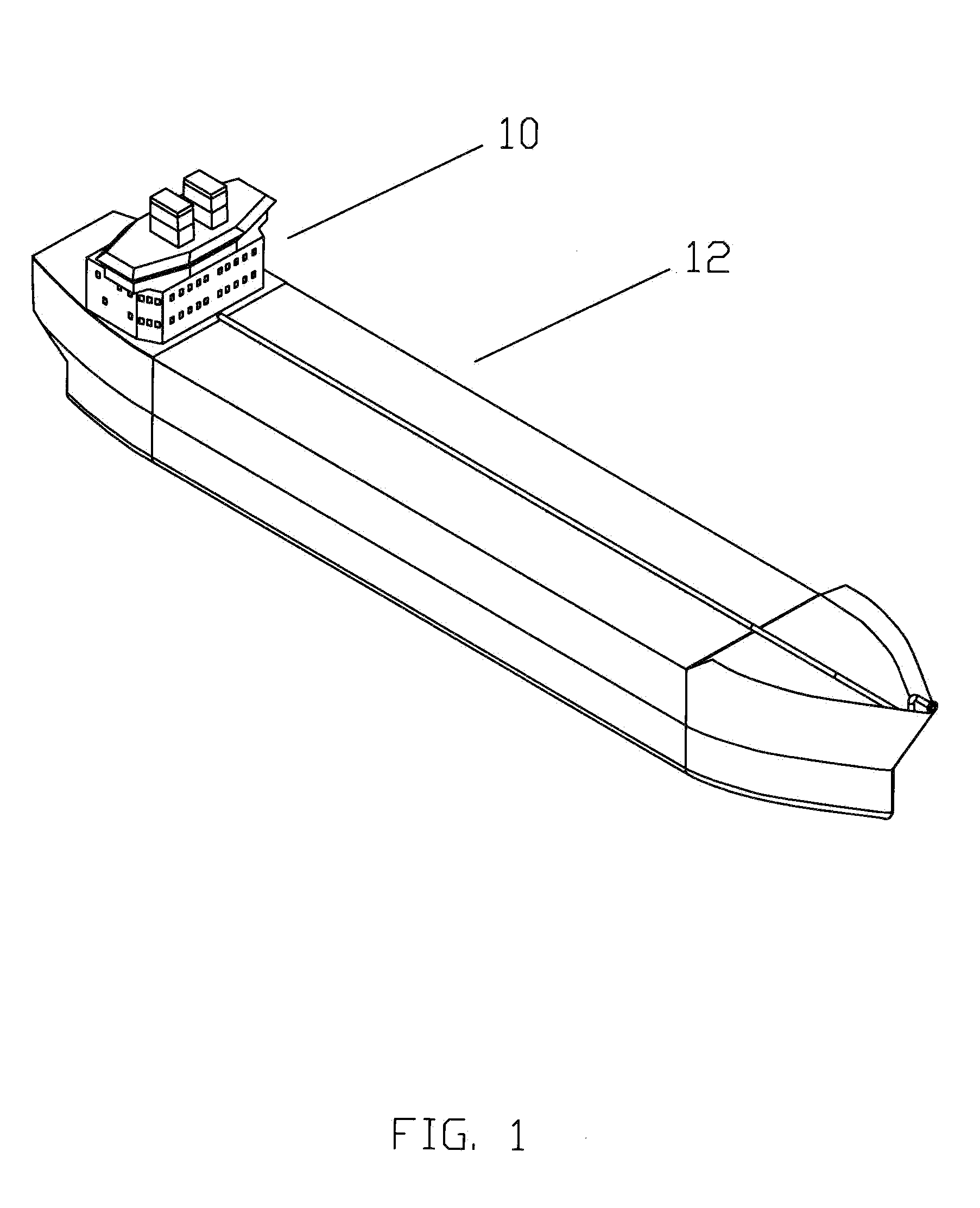
[0022]Referring now to FIG. 1, an offshore tanker 10 is shown which has a substantial central portion 12 which contains gas storage tanks.

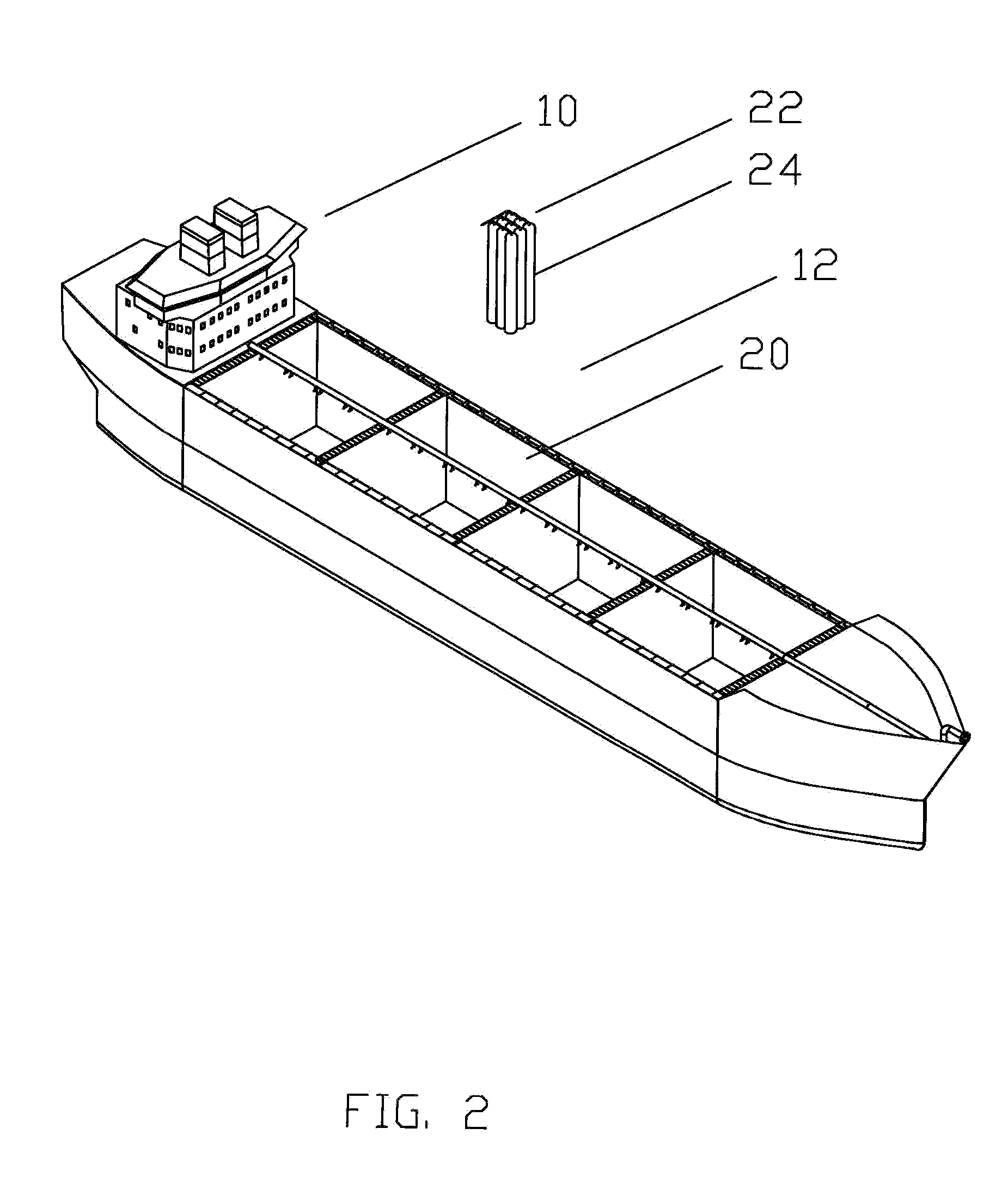
[0023]Now referring to FIG. 2, the offshore tanker 10 is shown with the top cover from the central portion 12 removed and showing a number of storage chambers 20. A bank of storage bottles 22 is shown with one of the individual bottles identified as 24. Individual bottles can be of a variety of sizes, for example 24 inches in diameter by 45 feet long.

[0024]Referring now to FIG. 3, offshore tanker 10 is shown with more of the double wall covering from central portion 12 removed and a full set of bottles 22 installed. In this model 576 of the bottles 24 are shown.

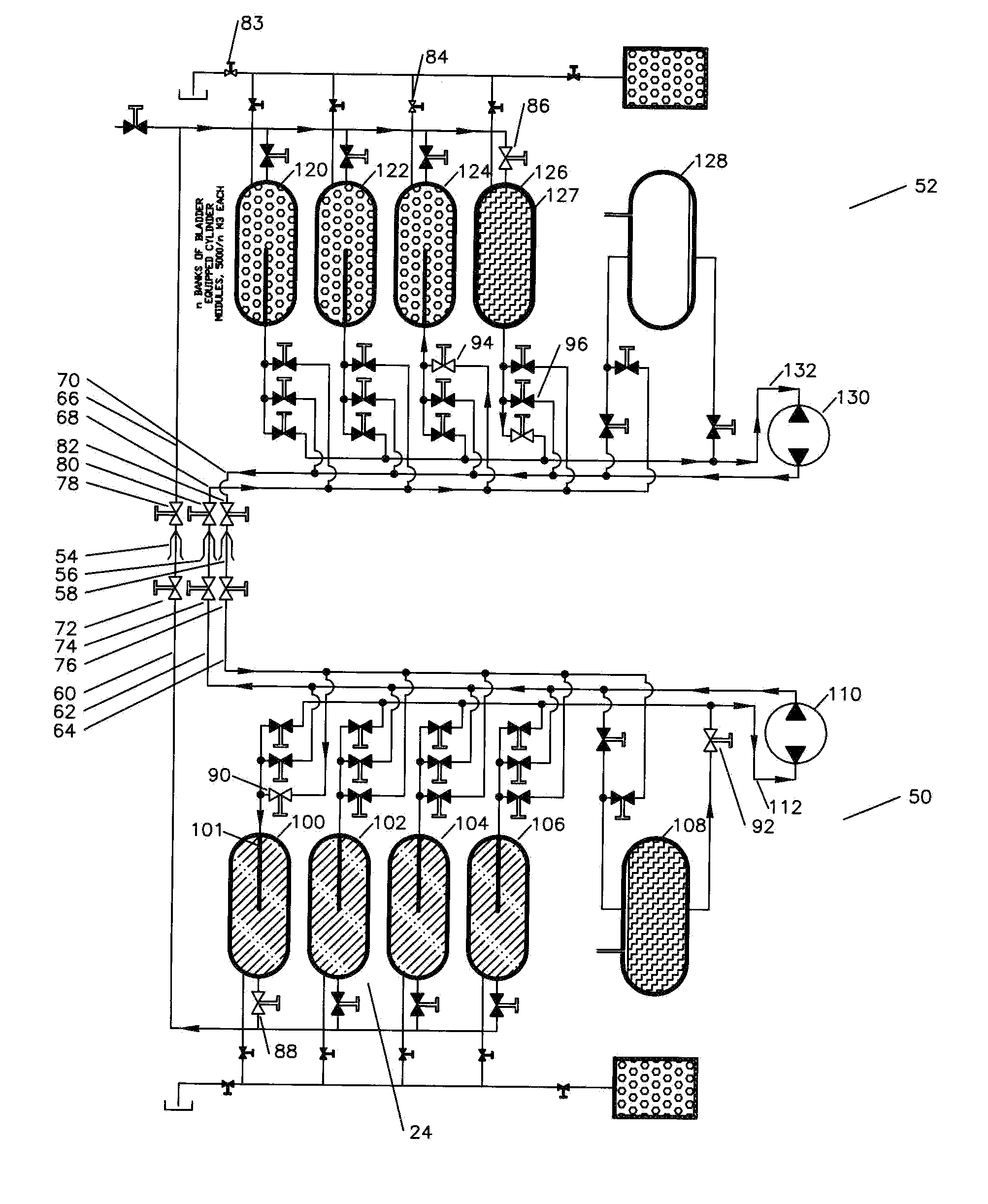
[0025]Referring now to FIG. 4, a graphic of the pumping system of this invention is shown. The lower portion of the graphic shows a transportation tank system 50 for transportation of the compressed gases and the upper portion shows a stationary tank system 52. The transportation tank syste...


PUM


Abstract

The method of transferring compressed gas at from a first tank to a second tank without decompressing the compressed gas and then re-pressuring the compressed gas comprising filling the second tank with a fluid, connecting a first fluid connection on the first tank to a second fluid connection on the second tank with a first line with one or more first valves, connecting a first gas connection on the first tank to a second gas connection on the second tank with a second line with one or more second valves, opening the first valves and the second valves to allow the compressed gas to pressurize the fluid, and pumping the fluid in the second tank into the first tank, thereby causing the compressed gas in the first tank to be displaced into the second tank.

Description

TECHNICAL FIELD[0001]This invention relates to the method expelling compressed gas from one or more compressed gas tanks, especially as associated with the transportation and delivery of compressed natural gas.BACKGROUND OF THE INVENTION[0002]The transportation of natural gas from the supply location to the tanks at the market by ship or truck transportation tanks requires that the gas be highly compressed to make the transportation economic. The expense of high pressure transportation tanks (e.g. 3000 p.s.i.) rather than at atmospheric pressure (e.g. 0 p.s.i.) is more than offset by the fact that about 250 times as much gas product can be transported.[0003]A second problem exists that if the tanks at the market have an intermediate pressure such as 600 p.s.i. When the 3000 p.s.i. high pressure transportation tanks are dumped into the market tanks, approximately 1780 p.s.i. will remain in the transportation tanks. This means that approximately 60% of the product transported remains ...

Claims


Application Information

Patent Timeline
Patent Type & Authority Applications(United States)
IPC IPC(8): F17C5/06
CPCF17C5/06F17C2205/0323F17C2205/0364F17C2223/0123F17C2225/0123F17C2260/02F17C2223/036F17C2227/041F17C2270/0105F17C2270/0171F17C2225/036F17C2201/0109F17C2201/018F17C2201/019F17C2201/032F17C2201/054F17C2205/0142F17C2205/0146F17C2205/0326F17C2205/0332F17C2221/033F17C2227/0192F17C2270/011F17C2270/0173
Inventor MOSZKOWSKI, MARCBAUGH, BENTON FREDERICK
Owner MOSZKOWSKI MARC
Why Eureka
Try Eureka