Method for producing polysilicon

a technology of polysilicon and polysilicon slurry, which is applied in the direction of silicon compounds, inorganic chemistry, chemistry apparatus and processes, etc., can solve the problems of large production facility itself, deformation or damage, and adverse effects of blocking valves, so as to facilitate maintenance of chemical reactors, prevent thermal degradation of blocking valves, and prevent adhesion effect of silylene polymers

Active Publication Date: 2020-04-02
TOKUYAMA CORP
View PDF0 Cites 0 Cited by
  • Summary
  • Abstract
  • Description
  • Claims
  • Application Information

AI Technical Summary

Benefits of technology

The present invention provides a way to prevent thermal degradation of a blocking valve in a waste gas pipe connected to a chemical reactor. This is achieved by adding a cooler of an indirect cooling type to a portion of the waste gas pipe between the chemical reactor and the blocking valve. This also allows for easier maintenance of the chemical reactor and prevents adhesion of silylene polymer to the cooler and downstream pipe. Overall, this invention improves safety and efficiency in the process of disconnecting a chemical reactor from a waste gas processing facility.

Problems solved by technology

Therefore, in a case where the waste gas at a temperature exceeding a heat-resistant temperature of the blocking valve reaches the blocking valve, the blocking valve may be adversely affected, i.e., deformed or damaged, for example.
Furthermore, in a case where the blocking valve is provided at a location distant from the waste gas outlet of the chemical reactor, a production facility itself can be large.
Moreover, the inventor of the present invention considered that rapid cooling of the waste gas could lead to excessive cooling of the waste gas, deposition of a silylene polymer, which is ignitable, and then adhesion of the silylene polymer to the waste gas pipe, resulting in blockage of the waste gas pipe.

Method used


Image

  • Method for producing polysilicon
  • Method for producing polysilicon

Examples


example

[0067]The present invention will be described below in more detail on the basis of an Example. Note, however, that the present invention is not limited to such an Example.

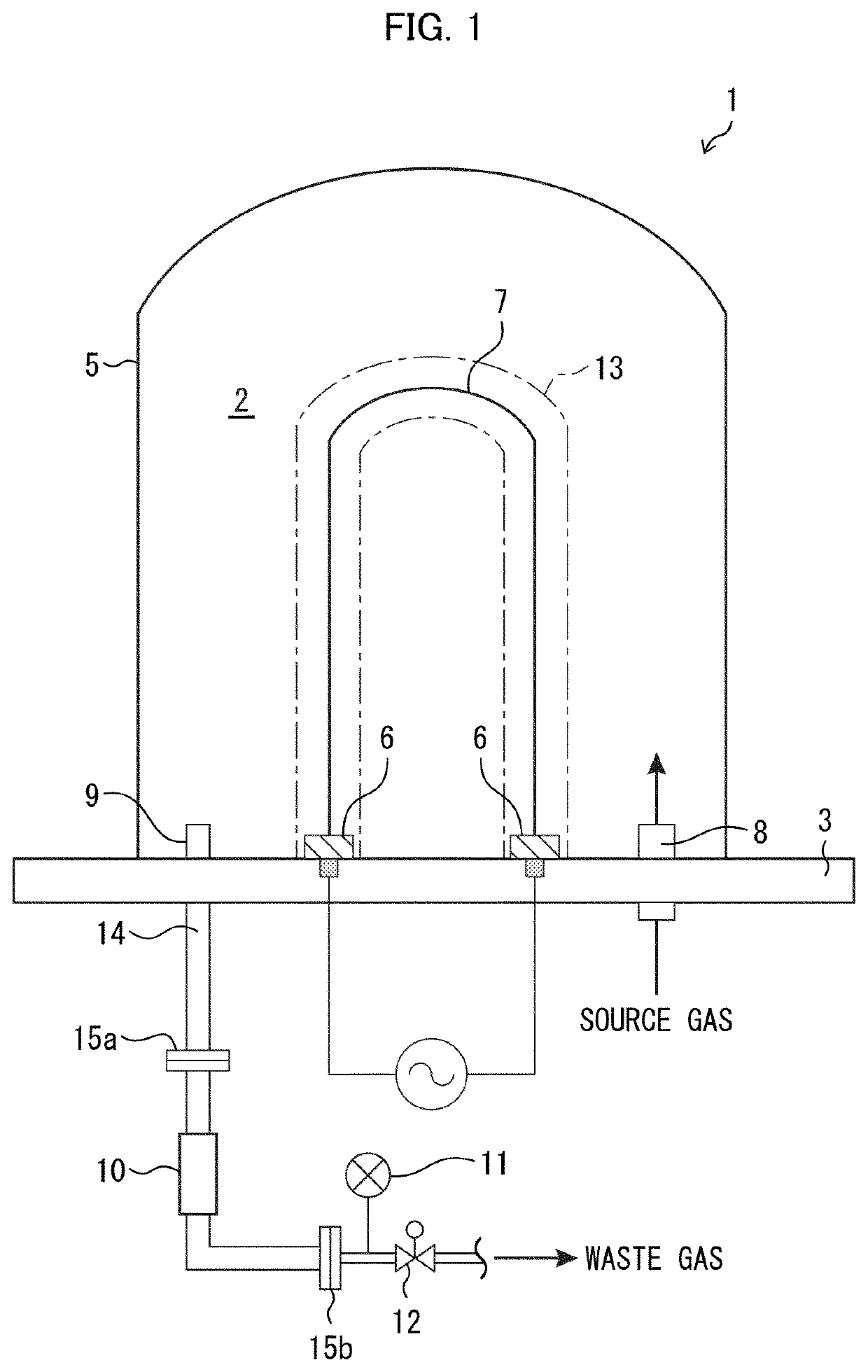
[0068]A bell-jar-shaped chemical reactor having a structure illustrated in FIG. 1 was used. After trichlorosilane and hydrogen were fed into the chemical reactor, electric power was supplied to a silicon filament with an electric current of not more than 2000 A so that a silicon deposition reaction was carried out.

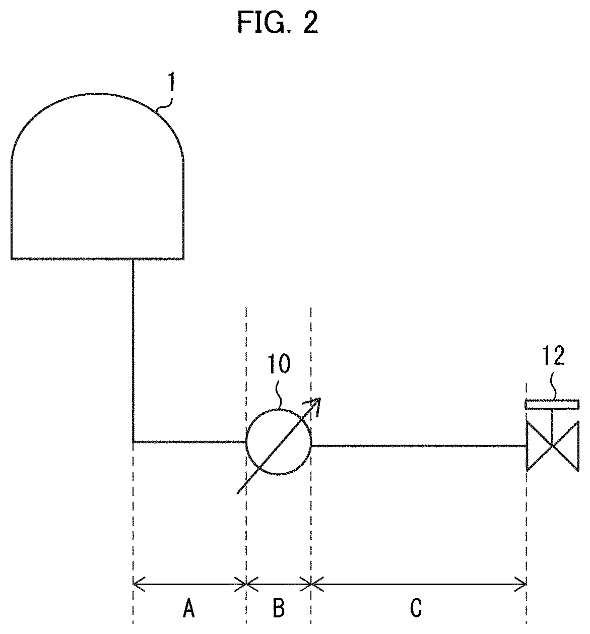
[0069]As a cooler, a U-tube cooler (shell and tube cooler) was used. As a blocking valve, a gate valve made of stainless steel (having a heat-resistant temperature of 500° C.) was used.

[0070]With use of the above device, the silicon filament was heated to approximately 800° C. by supply of electric power to the silicon filament, while a trichlorosilane gas and a hydrogen gas were being fed into the chemical reactor. Polysilicon was thus deposited until the polysilicon had a diameter of 120 mm. In so doing...


PUM

PropertyMeasurementUnit
temperatureaaaaaaaaaa

Abstract

A method for efficiently producing polysilicon is realized. The present invention is an invention of a method for producing polysilicon by the Siemens process, a chemical reactor being connected to a waste gas processing facility via a blocking valve provided to a waste gas pipe, the blocking valve being provided in a vicinity of a waste gas outlet of the chemical reactor, the method including the step of cooling a waste gas between the waste gas outlet of the chemical reactor and the blocking valve, with use of a cooler of an indirect cooling type.

Description

TECHNICAL FIELD[0001]The present invention relates to a method for producing polysilicon.BACKGROUND ART[0002]As a method for industrially producing polysilicon used as a raw material of a semiconductor or a wafer for photovoltaic power generation, the Siemens process is known. According to the Siemens process, a source gas composed of hydrogen and trichlorosilane is fed into a bell-shaped (bell-jar-shaped) chemical reactor, and a filament for depositing polysilicon thereon, which filament is provided in a standing manner in the chemical reactor, is heated so that polysilicon is deposited on a surface of the filament. Thereafter, the polysilicon is grown to produce a polysilicon rod. A waste gas generated during the above deposition reaction generally contains chlorosilanes (such as unreacted trichlorosilane; tetrachlorosilane generated during the deposition reaction; dichlorosilane generated during the deposition reaction as a by-product; and a silylene polymer), unreacted hydrogen,...

Claims


Application Information

Patent Timeline
Patent Type & Authority Applications(United States)
IPC IPC(8): C01B33/035
CPCC01B33/035
Inventor KAMADA, MAKOTO
Owner TOKUYAMA CORP
Why Eureka
Try Eureka