
Interconnect for implantable medical device header

a medical device and header technology, applied in the direction of coupling device connection, contact member manufacturing, therapy, etc., can solve the problems of inability to test the electrical integrity of the unit, the system also suffers from similar drawbacks to those described, and the over-molding is extensive, so as to facilitate assembly, reduce the amount of backfill, and facilitate backfilling

Active Publication Date: 2007-09-25
CARDIAC PACEMAKERS INC
View PDF15 Cites 111 Cited by
  • Summary
  • Abstract
  • Description
  • Claims
  • Application Information

AI Technical Summary

Benefits of technology

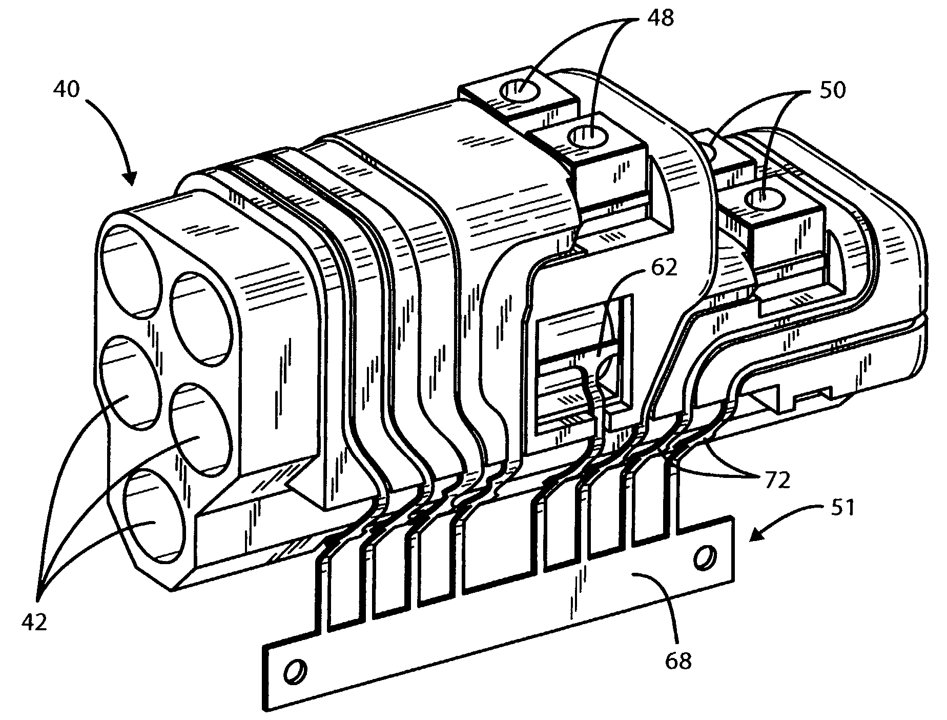
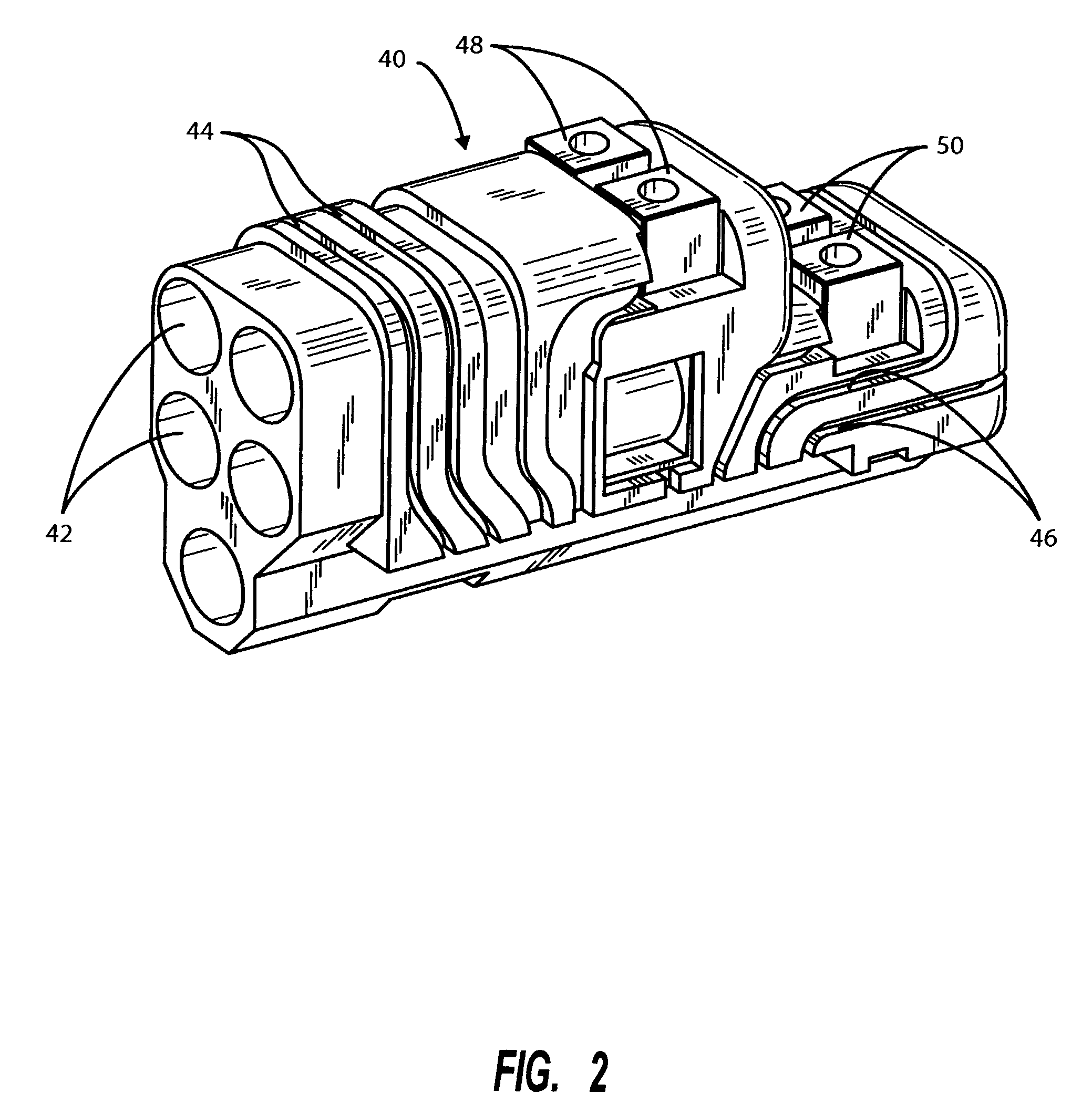
[0007]By means of the present invention there is provided a module header sub-assembly for assembly to in connection with a hermetically sealed implantable medical device which solves many of the above problems and overcomes the drawbacks of previous versions of such devices. The present invention provides the desired electrical feed-through, but, unlike previous header units, the header of the present invention is a sufficiently complete sub-assembly such that it can be tested for functional integrity prior to assembly onto the hermetically sealed medical device. The present header also facilitates assembly and reduces the amount of necessary backfill.
[0009]The reduction of the volume required to be backfilled after welding operations also eliminates concerns with respect to the sealing integrity of the backfill which is currently dependent on the technique and skill of the operator and the subsequent inspection. The pre-fabricated wire terminations further eliminates a major manufacturing step involved in routing and backfilling of the wire channels in the header and further allows testing of the integrity of each conductor in the header prior to assembly of the header to the hermetically sealed device. Since the flex / conductor system can be an integral part of the header, mold / sealing operations requiring high pressures are now possible since the header does not have to be connected to the device prior to these primary or secondary mold / seal operations.

Problems solved by technology

That system, however, still depends on the skill of workers for assembly and requires extensive over molding.
Furthermore, the electrical integrity of the unit cannot be tested until it is completely assembled.
This system also suffers from similar drawbacks to those described above.

Method used


Image

  • Interconnect for implantable medical device header
  • Interconnect for implantable medical device header
  • Interconnect for implantable medical device header

Examples


Embodiment Construction

[0019]It will be appreciated that the present invention enables the header to be built as a complete modular sub-assembly capable of being tested for circuit integrity prior to attachment to the feed-through pins of the hermetically sealed pacer, other IPG or other implanted unit. The present invention also greatly simplifies the connection process and reduces the amount of backfilling required to complete the header / hermetically sealed IPG assembly. While the detailed description which follows is limited to one or two embodiments, it will also be understood that these are intended as examples only and are not intended to limit the scope of the inventive concept in any manner.

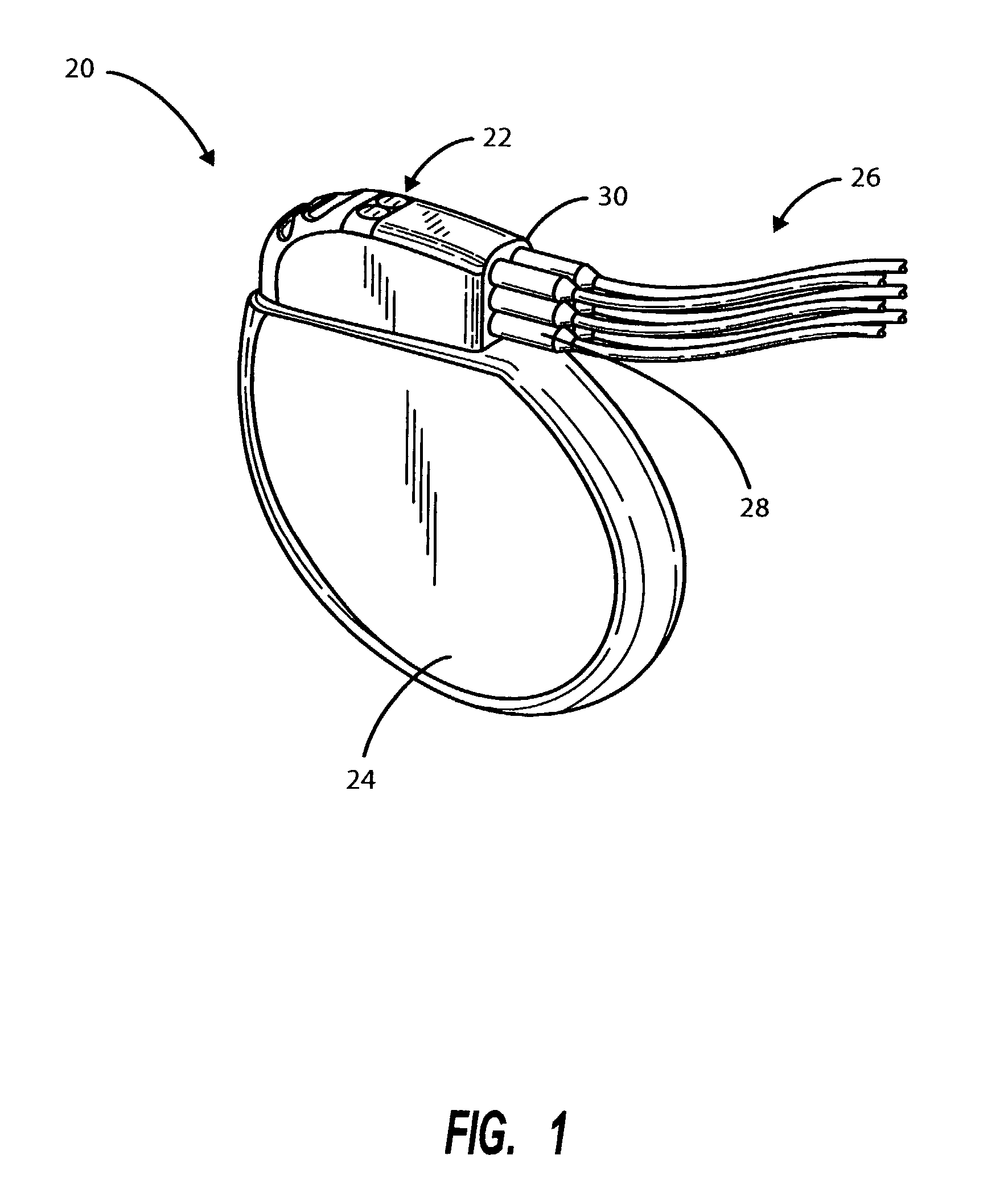
[0020]FIG. 1 depicts a simplified schematic view of an implantable medical device 20 of a class suitable for utilizing the header of the present invention including a pre-formed, pre-assembled header module 22 attached to a hermetically sealed enclosure 24. A plurality of leads 26, which typically include atria...


PUM


Abstract

A modular header and method of fabricating same for making electrical connection between an array of feed-through pins extending through a wall of a hermetically sealed enclosure of an implantable medical device and lead connector receptacles within the header in which the header is fabricated using a pre-formed molded header module, together with a set or harness of interconnected flexible conductors incorporated and sealed by an overlayer of medical grade polymer material. The assembled modular header is capable of complete pretesting prior to assembly onto an implantable medical device.

Description

BACKGROUND OF THE INVENTION[0001]I. Field of the Invention[0002]The present invention relates generally to implantable medical devices having external electrical connections and electrical feed-throughs and, more particularly, to the provision of a pre-built modular sub-assembly interconnect system for a header module such as are found in implantable pulse generators (IPG's) associated with cardiac rhythm management and other hermetically sealed implantable medical devices.[0003]II. Related Art[0004]Implantable medical devices of a class having electrical circuit components are well known in the medical field. These include cardiac rhythm management devices which commonly include a pacemaker unit which, in turn, includes sensing and control circuitry, together with a power supply, protectively housed in a hermetically sealed case or can in combination with one or more conductive electrical leads designed to connect to the patient's heart muscle tissue, the activity of which is to be...

Claims


Application Information

Patent Timeline
Patent Type & Authority Patents(United States)
IPC IPC(8): A61N1/372A61N1/375
CPCA61N1/3752Y10S439/909H01R13/504A61N1/3754H01R43/005H01R43/16H01R43/18
Inventor SPADGENSKE, SCOTT A.
Owner CARDIAC PACEMAKERS INC
Learn More