Non-Slip Fuel Tank Bracket

a fuel tank and bracket technology, applied in the field of storage tanks, can solve the problems of high pressure gas line breakage, prone to movement, subject to ‘g’ forces, etc., and achieve the effect of increasing frictional resistance and arresting movemen

Active Publication Date: 2015-04-09
QUANTUM FUEL SYSTEMS LLC
View PDF28 Cites 32 Cited by
  • Summary
  • Abstract
  • Description
  • Claims
  • Application Information

AI Technical Summary

Benefits of technology

[0011]Some aspects of exemplary implementations of the disclosure provide wedge-shaped gaskets and intermediate sliders that are placed on the tank body and in between the U-shaped straps and L-shaped brackets and the tank body. If the tank body were to slide longitudinally, the wedge-shape imposes additional pressure on the tank body, exponentially increasing the frictional resistance between the tank body and the strap / bracket, thereby arresting the movement.
[0012]Additionally, a circumferential wedge-shaped gasket is bonded to the tank body at the gap between the U-shaped strap and L-shaped bracket. The wedge-shaped gasket can also be secured in place using epoxy or polyurethane impregnated fiber glass cloth. This wedge-shaped gasket prevents rotation of the tank body, since frictional resistance against rotation increases with rotational displacement as the wedge creates added pressure on the tank body's external shell.
[0013]Some aspects of exemplary implementations of the disclosure provide wedge-shaped gaskets configured to interact with the tank body and U-shaped straps and L-shaped brackets that help prevent relative movement of the tank body. The body can be secured to a frame, and the frame can be a part of a vehicle, such as an automobile, truck, bus, locomotive or a marine vessel. The intermediate slider that is deployed between the wedge-shaped gasket and the U-shaped strap or L-shaped bracket has ridges on the surface that contacts the bracket segments, thereby securing the brackets.

Problems solved by technology

The high pressure tanks expand and contract during refueling and engine fuel consumption cycles, and are subject to ‘g’ forces induced by vehicle acceleration, deceleration, extended vibrations and collisions.
Tanks that are mounted longitudinally (i.e., parallel to the vehicle axis) are especially prone to movement within the brackets either axially or rotationally, under repeated ‘g’ loads and expansion-contraction cycles.
For example, cylindrical fuel tanks which are mounted longitudinally on the roofs of buses or on the side of trucks may be prone to longitudinal sliding or hoop spinning within the brackets, causing breakage of high pressure gas lines affixed to the tanks.
This is a challenge especially for heavy tanks since the ‘g’ force is a product of the tank mass and the vehicle acceleration.
However, these conventional gaskets do not prevent lateral movement or rotation of the tank.
However, the tanks can still move laterally.
Unfortunately, the pressure applied by the bracket on the tank decays with time, due to relaxation of the bracket material and loosening of the U-L joint under tank expansion-contraction cycles and repeated ‘g’ forces.
As a result of the reduced frictional resistance between the brackets and the tank, the tank may slide longitudinally and or rotate, creating the safety hazard of gas line breakage.

Method used


Image

  • Non-Slip Fuel Tank Bracket
  • Non-Slip Fuel Tank Bracket
  • Non-Slip Fuel Tank Bracket

Examples


Embodiment Construction

[0030]The following detailed description is of the best presently contemplated modes of carrying out the invention. This description is not to be taken in a limiting sense, but is made merely for the purpose of illustrating general principles of embodiments of the invention. The scope of the invention is best defined by the appended claims.

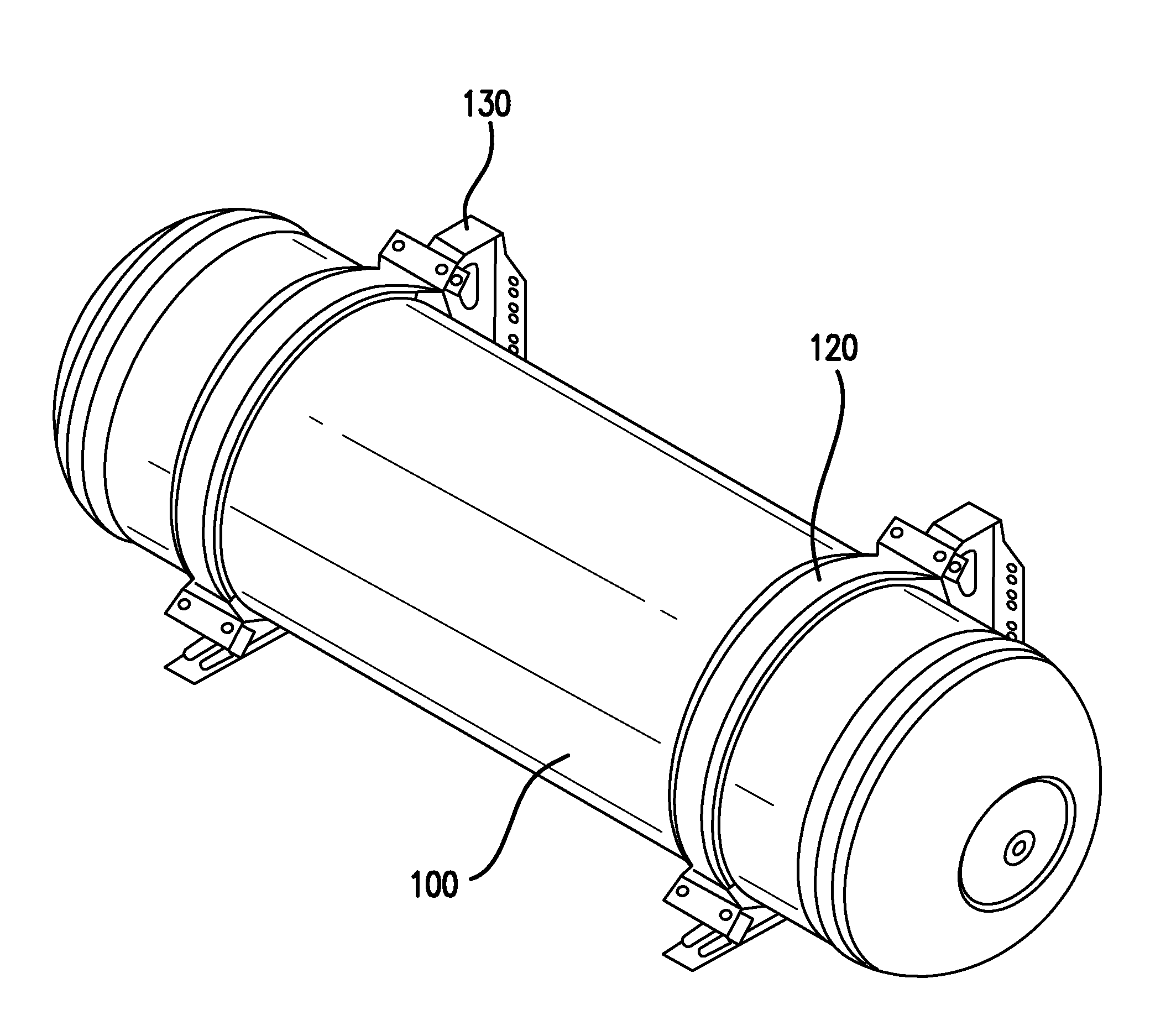
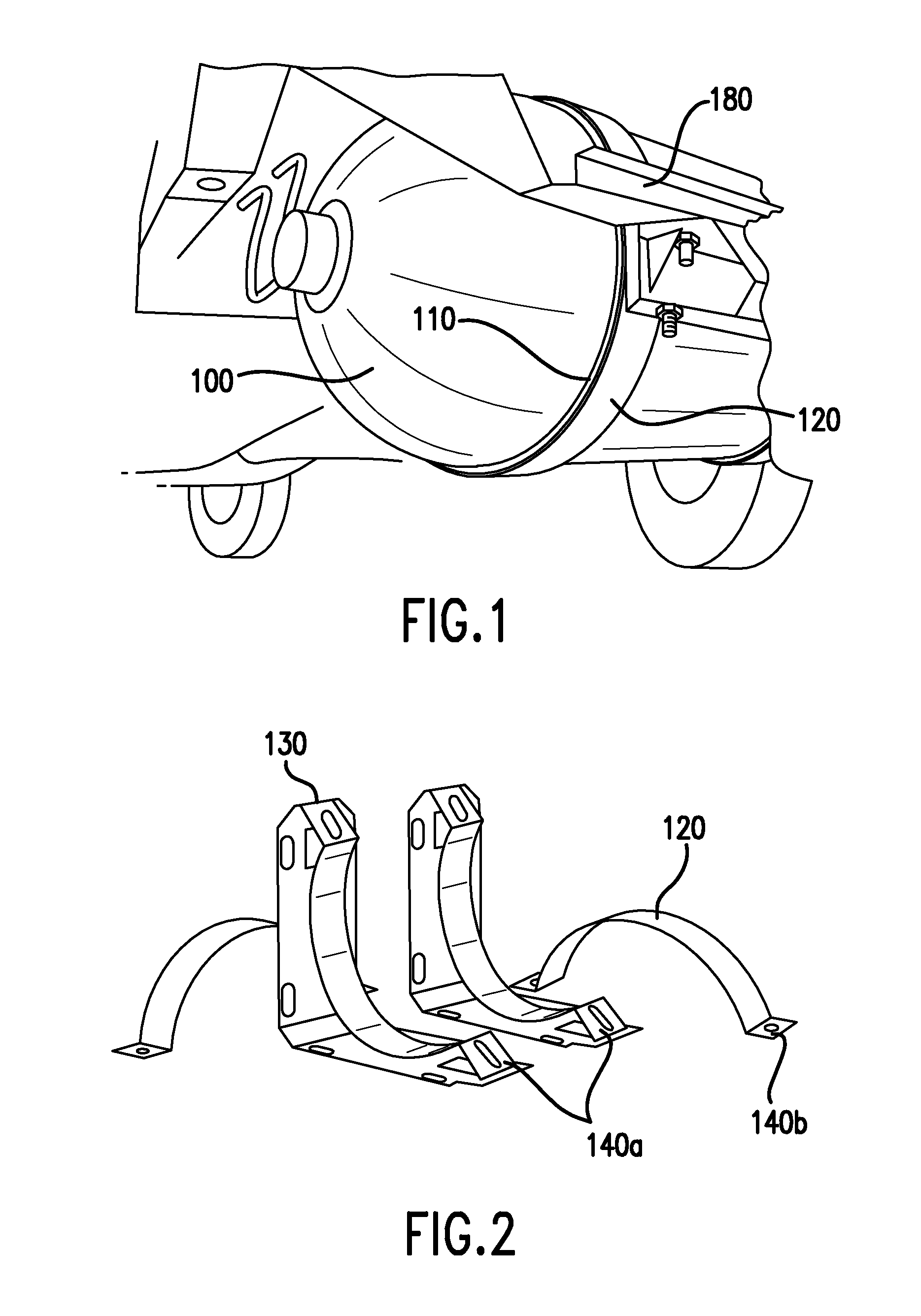
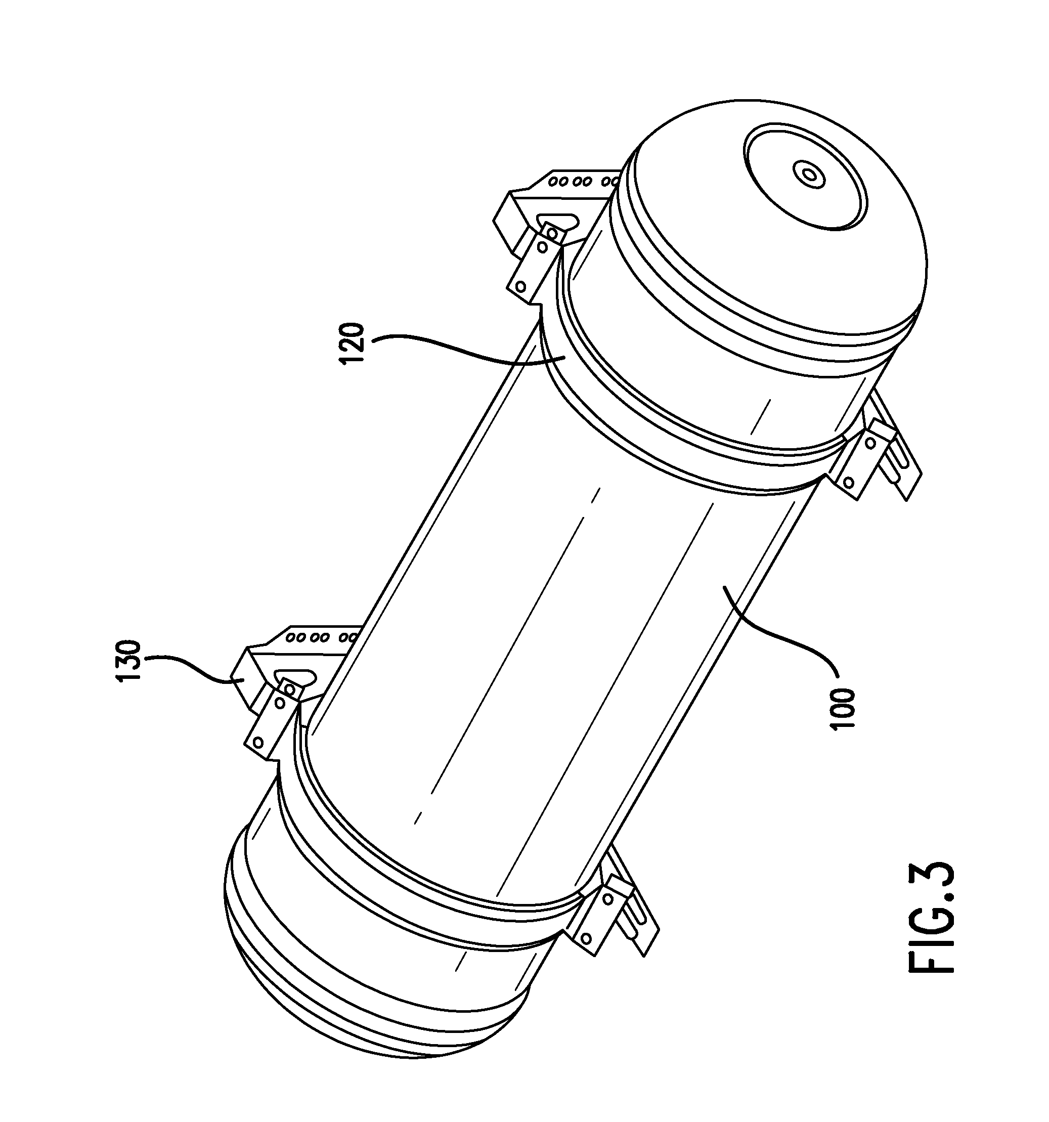
[0031]The present invention provides systems and devices for preventing longitudinal sliding and rotation of cylindrical fuel tanks while secured by the brackets attached to vehicular frames. Various aspects of the invention described herein may be applied to any of the particular applications set forth below or for any other types of securing systems. The present invention may be applied as a stand-alone system or method, or as part of a vehicle or other system that utilizes fuel.

[0032]Some aspects of the present invention provide wedge-shaped gaskets and sliders that are placed on cylindrical fuel tanks, vessels, or any other type of device capa...


PUM


Abstract

A fuel holding device is secured to a vehicle by means of straps and brackets, which sits on a system of gaskets to prevent longitudinal sliding and rotation. A gasket system for preventing longitudinal sliding is disposed circumferentially around the tank body, and between the tank body and a circumferential bracket system that includes a U-shaped strap and an L-shaped bracket. The gasket system comprises a wedge-shaped base and a slider portion, with the U-shaped strap secured around the slider portion. A system for preventing rotation of a fuel-holding device has a circumferential wedge gasket segment, or a corrugated segment, positioned at a gap between the U-shaped strap and the L-shaped bracket.

Description

BACKGROUND OF THE INVENTION[0001]1. Field of the Invention[0002]This invention relates to storage tanks used for storing compressed gaseous fuels. In particular, the present invention is related to a mechanism for preventing the relative movement of tanks that are attached to vehicles using hoop brackets to safeguard against high pressure line breakages.[0003]2. Description of the Prior Art[0004]Cylindrical fuel tanks, such as compressed natural gas and compressed hydrogen gas tanks, are typically secured to the vehicle structure using hoop brackets. The high pressure tanks expand and contract during refueling and engine fuel consumption cycles, and are subject to ‘g’ forces induced by vehicle acceleration, deceleration, extended vibrations and collisions. Tanks that are mounted longitudinally (i.e., parallel to the vehicle axis) are especially prone to movement within the brackets either axially or rotationally, under repeated ‘g’ loads and expansion-contraction cycles.[0005]For ex...

Claims


Application Information

Patent Timeline
Patent Type & Authority Applications(United States)
IPC IPC(8): F02M21/02B60K15/03B60R16/08B60K5/00F16B2/08F16B2/14
CPCF02M21/0221F16B2/08F16B2/14B60K15/03006B60K5/00F02M21/0296B60R16/08B60K15/07B60K2015/0638F02M21/029Y02T10/30
Inventor SIROSH, NEELOLISCHEFSKI, DERRIN LYNN
Owner QUANTUM FUEL SYSTEMS LLC
Why Eureka
Try Eureka